Picture a 400G data center rack managing 576 fiber connections in a single 1U panel. The facility operator faces a choice: deploy hundreds of individual LC duplex cables creating pathway congestion, or leverage multi-fiber technology that consolidates the same capacity into 48 connector interfaces. This density challenge defines modern network architecture. As bandwidth requirements scale from 100G to 800G and beyond, the infrastructure supporting these speeds must deliver corresponding spatial efficiency without compromising signal integrity.
MTP/MPO systems address high-density requirements through multi-fiber array connectivity, consolidating 8 to 72 individual fibers within a single connector interface roughly the size of a standard duplex LC. These mtp mpo connectors maintain physical dimensions comparable to SC connectors while increasing fiber density by factors of 6x to 36x, enabling data centers to achieve port counts previously impossible with traditional single-fiber architectures. The technology supports 40G through 800G transmission rates while reducing cable footprint and streamlining installation through pre-terminated assemblies.
The Density Economics: Why Multi-Fiber Architecture Matters
Data center real estate operates under severe spatial constraints. High-performance computing environments face costs measured per square foot where every rack unit translates to revenue-generating compute capacity. Traditional cabling approaches using individual fiber pairs create compounding density problems as speeds increase-a 400G link requiring 8 fiber pairs would need 8 separate duplex connections, consuming excessive panel space and pathway volume.
Multi-fiber push-on technology fundamentally changes this equation. An mtp mpo connector occupying 12.5mm x 7.6mm can replace eight individual duplex LC connectors, recovering approximately 75% of panel real estate. This consolidation extends beyond connector interfaces-trunk cables employing MTP/MPO terminations significantly reduce pathway fill compared to equivalent duplex cable bundles.
The architectural advantage compounds in structured cabling deployments. A 1U patch panel using MTP/MPO-12 cassettes can terminate 144 LC duplex connections (288 fibers), while a 4U configuration scales to 576 ports. These density levels enable spine-leaf topologies with simplified cable management and reduced installation labor compared to conventional approaches.
Recent standards evolution supports even higher density requirements. Very small form factor (VSFF) connectors including MMC-16 and SN-MT provide approximately 3x the density of traditional 16-fiber mtp mpo systems, accommodating 216 ports in 1U versus 80 ports with standard MTP/MPO-16. This advancement specifically targets hyperscale and AI cluster deployments where space constraints are most acute.
Technical Foundation: How Multi-Fiber Connectivity Achieves Density
MT Ferrule Precision Engineering
The mechanical transfer (MT) ferrule forms the core enabling technology for high-density multi-fiber connections. This monolithic glass-filled polymer component measures 6.4mm x 2.5mm with fiber pitch standardized at 0.25mm, terminating 8 to 16 fibers in a single row through high-precision molding. Unlike ceramic ferrules employed in single-fiber connectors, the polymer composition allows simultaneous multi-fiber termination while maintaining tight tolerances.
Guide pin holes with positioning accuracy to within micrometers ensure fiber alignment between mated connectors, while spring mechanisms provide consistent normal force. This mechanical design enables repeatable connections with insertion loss below 0.35 dB per mating interface for premium-grade connectors.
Standards bodies including IEC and TIA define dimensional specifications ensuring interoperability across manufacturers. IEC 61754-7 and TIA-604-5 (FOCIS-5) establish physical parameters for pin dimensions, guide hole geometry, and ferrule flatness, creating a standardized ecosystem supporting multiple vendor implementations.
Fiber Count Configurations and Application Mapping
MTP/MPO connectors are available in 8, 12, 16, 24, 32, 48, 60, and 72-fiber configurations, with different counts optimized for specific network speeds and topologies:
8-Fiber Configuration: Primarily employed in 40G SR4 applications where only 4 transmit and 4 receive lanes are utilized. This count eliminates unused dark fibers present in 12-fiber implementations. 8-fiber connectors optimize port usage and can split into two 4-fiber duplex channels for specialized breakout scenarios.
12-Fiber Standard: The most widely deployed configuration for legacy 40G and 100G Ethernet. 100G SR4 utilizes 8 of 12 available fibers, leaving 4 unused but providing standardized infrastructure compatibility. The 12-fiber MT ferrule represents the original industry standard with broadest ecosystem support.
16-Fiber Architecture: Specifically designed for 400G SR8 applications using 8 transmit and 8 receive lanes with full fiber utilization. The 16-fiber mtp mpo configuration employs offset keying that prevents accidental mating with 12-fiber hardware, ensuring proper polarity management. This count is becoming the preferred choice for 400G deployments.
24-Fiber Density Champion: Supports 800G SR8 using 16 active fibers with 8 spare for additional links or future use, configured in two 12-fiber rows. The dual-row design maintains the same connector footprint as single-row versions while doubling fiber capacity. In QSFP applications, 24-fiber connectors can achieve 8x panel density increase versus 12-fiber implementations.
Higher Counts (32-72 fibers): These specialized configurations target large-scale optical switches and extremely high-density multi-fiber arrays in hyperscale environments. Multiple-row ferrule designs accommodate these counts while maintaining mechanical compatibility standards.
Parallel Optics: The Bandwidth Multiplier
Traditional duplex fiber operates on wavelength division or time division multiplexing to increase throughput. Parallel optics takes a fundamentally different approach-simultaneously transmitting multiple independent data streams across separate fiber pairs. 40GBASE-SR4 transmits 4 lanes at 10 Gb/s each, while 100GBASE-SR4 operates 4 lanes at 25 Gb/s, aggregating to achieve target speeds.
400G-SR8 employs 8 transmit lanes and 8 receive lanes, each operating at 50 Gb/s, aggregating to 400 Gb/s total throughput. This parallel transmission architecture requires precise fiber management-each transmit fiber must correctly map to its corresponding receive fiber at the far end. Polarity management methodologies (Types A, B, C, and newer U1/U2 standards) address this requirement through standardized connector configurations and key orientations.
The parallel approach offers distinct advantages for short-reach applications typical in data centers. Multimode fiber with mtp mpo connectors enables transmission distances of 100-150 meters for 400G applications, adequate for intra-rack and rack-to-rack connectivity while avoiding the cost and power consumption of active wavelength multiplexing.

MTP Enhancement: Engineering for Performance at Scale
Mechanical Improvements Over Generic MPO
US Conec's MTP (Multi-fiber Termination Push-on) represents an engineered evolution of the generic MPO connector standard. Key enhancements include metal pin clamps replacing plastic versions, floating ferrule design for improved physical contact, and tightened manufacturing tolerances. These changes directly address failure modes observed in high-volume deployments.
The floating ferrule mechanism allows two mated ferrules to maintain physical contact under applied load, compensating for minor alignment variations and maintaining consistent insertion loss. This design reduces signal degradation in installations experiencing thermal cycling or mechanical stress.
Pin retention represents another critical improvement. Standard MPO connectors employ plastic pin clamps that may break with repeated mating cycles, while MTP metal clamps provide stronger retention minimizing pin damage. In environments requiring frequent reconfigurations, this durability advantage translates to reduced maintenance and lower long-term costs.
Insertion Loss Performance Tiers
Connector grade significantly impacts optical performance, with three tiers defined by maximum insertion loss specifications:
Standard Grade: Maximum IL of 0.50 dB, typical for MPO connectors meeting baseline standards. Adequate for 10G and some 40G applications but may not satisfy loss budgets for longer 100G+ links.
Low-Loss Grade: Maximum IL of 0.35 dB, standard for quality MTP connectors. This performance tier supports 100G and 400G applications across typical data center link distances.
Elite Grade: Maximum IL of 0.25 dB with return loss exceeding 60 dB. Elite ferrules employ enhanced polishing and tighter geometry specifications. MTP Elite can reduce insertion loss by up to 50% compared to standard MPO connectors.
In 400G deployments with 1.9 dB total channel loss budgets, connector grade selection can consume up to half the available loss budget. Elite-grade selection enables longer spans or accommodates additional connection points without exceeding loss limits.
Return loss (RL) equally influences system performance, particularly for VCSEL-based transceivers sensitive to back-reflection. Elite MTP maintains RL above 60 dB versus approximately 30 dB for standard MPO, stabilizing laser output and reducing jitter in high-speed applications.
Deployment Architectures: From Trunk to Breakout
Structured Cabling with MTP/MPO Trunk Systems
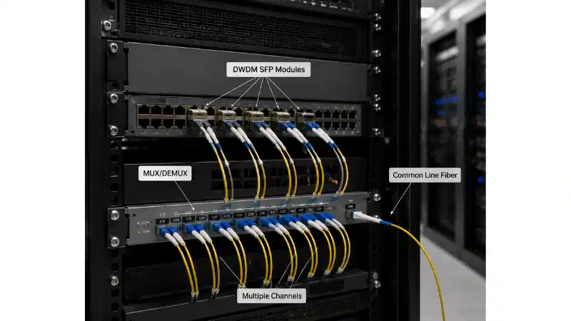
MTP/MPO-terminated trunk cables form permanent backbone links between distribution areas, transitioning to individual duplex connections at patch panels through cassettes or hybrid cords. This architecture separates high-density aggregation from flexible patching zones.
Typical deployment employs 12 or 24-fiber trunk cables between main distribution areas (MDA) and horizontal distribution areas (HDA). Factory-prepared trunk assemblies reduce installation time by 80% compared to field termination, eliminating on-site splicing while ensuring consistent polarity and performance.
At patch panels, cassette modules convert mtp mpo interfaces to individual LC duplex ports. A 12-fiber MTP cassette provides 6 LC duplex connections, while 24-fiber versions yield 12 duplex ports. This modular approach enables easy reconfiguration-changing network architecture requires swapping cassettes rather than re-terminating individual fibers.
The star topology commonly employed in data centers benefits particularly from trunk cable density advantages. High-density cabling reduces pathway congestion by over 50% compared to traditional approaches, simplifying adds/moves/changes while improving airflow around cable bundles.
Breakout Cables: Bridging Speed Transitions
Breakout (harness) cables feature MTP/MPO on one end and multiple lower-density connectors (typically LC) on the other, facilitating speed transitions between equipment generations. Common configurations include:
MTP-12 to 6x LC Duplex: Supports transitions from 40G or 100G trunk to six 10G or 25G server connections. This breakout enables oversubscription ratios in leaf-spine architectures where aggregation switches employ higher-speed uplinks than server-facing ports.
MTP-16 to 8x LC Duplex: Designed for 400G to 100G breakout scenarios, particularly connecting 800G switch ports to dual 400G endpoints or eight 100G connections. This configuration addresses bandwidth allocation in AI/ML clusters with mixed-speed requirements.
MTP-24 to 2x MTP-12: Enables a single 800G link to split into two 400G connections while maintaining fiber efficiency. Dual MTP-12 terminations provide compatibility with existing 400G infrastructure during incremental upgrades.
Breakout cables simplify topology compared to using separate trunk cables plus patch cords. They reduce total equipment count by eliminating intermediate patch panels for speed conversion, though at the cost of reduced reconfiguration flexibility versus cassette-based approaches.
Real-World Density Impact: Quantified Deployment Scenarios
Case Study: Regional Financial Services Provider Rack Consolidation
A 350-person financial services firm operating a regional data center faced rack space exhaustion during a 10G to 100G network upgrade. Legacy cabling employed individual LC duplex connections between 96 edge switches and core aggregation infrastructure, consuming five 42U racks for cable management.
The migration to MTP/MPO-12 trunk cables with LC cassettes reduced cabling infrastructure to 1.5 racks-a 70% space recovery. Pre-terminated trunk assemblies enabled installation completion in 3 days versus projected 2 weeks for field termination. Insertion loss measurements averaged 0.28 dB per connection, well within 100GBASE-SR4 loss budgets.
Cost analysis revealed 40% reduction in total cabling expenditure despite mtp mpo components carrying price premiums over LC hardware. Labor savings from pre-terminated solutions and eliminated splicing dominated the economic calculation. Recovered rack space was redeployed for additional compute infrastructure generating estimated $180,000 annual revenue.
Case Study: SaaS Company 400G Spine Upgrade
A B2B SaaS provider operating a 5,000-server environment implemented MTP/MPO-16 infrastructure during a spine layer upgrade from 100G to 400G. The deployment employed 16-fiber trunk cables between spine and leaf switches, with breakout cables to existing 100G server connections.
MTP-16 configuration eliminated dark fibers present in 12-fiber 400G implementations, reducing material costs by 25% compared to alternative designs. The offset keying of 16-fiber connectors prevented accidental cross-connections with legacy 12-fiber infrastructure, simplifying operations.
Measured insertion loss averaged 0.31 dB using Elite-grade MTP connectors. This performance supported link lengths up to 125 meters, adequate for the facility's row-to-row distances. Total project timeline: 8 weeks including testing, versus 16-week estimate for traditional cabling.
Space savings enabled consolidation from 8 spine switches to 6 higher-port-count units with equivalent aggregate capacity. This reduction lowered power consumption by 18 kW and simplified routing protocols.
Case Study: Professional Services Firm Hybrid Deployment
A 280-person legal practice deployed mtp mpo cabling in a partial infrastructure refresh, maintaining existing 10G edge infrastructure while upgrading core and distribution layers to 100G. The hybrid approach employed MTP-12 trunks in the core with breakout cables to legacy LC connections.
Modular cassettes enabled easy migration path-as edge switches reach end-of-life, LC patching transitions to direct MTP connections without re-cabling trunks. This phased approach distributed capital expenditure across three budget cycles while maintaining operational continuity.
Installation time: 4 days for core infrastructure covering 180 fiber connections. Zero service interruption during deployment through staged cutover process. Measured improvement: 60% reduction in cable pathway congestion enabled improved airflow, reducing HVAC requirements by 12%.
Polarity Management: The Hidden Complexity
High-density multi-fiber systems introduce significant polarity challenges absent in duplex connections. TIA-568 defines three standard connection methods (Types A, B, C) plus newer universal methods (U1, U2) to ensure correct transmit-receive pairing. Each methodology employs different cable structures and mating approaches:
Type A (Straight-Through): Fiber 1 at one end connects to fiber 1 at far end. Requires two crossover points in the channel-typically at cassettes. Most common in legacy deployments.
Type B (Key-Up to Key-Up): Employs reversed cable construction. Position 1 at one connector maps to position 12 at the far end. Simpler to implement with fewer infrastructure components but requires careful documentation.
Type C (Pair-Flipped): Uses array flipping at one connector. Less common in modern deployments due to limited component availability and complexity in troubleshooting.
U1/U2 Universal Methods: Recently introduced standards simplify installations by supporting both duplex and parallel transmission with single cable types. Reduced component variation streamlines inventory and deployment processes.
Polarity errors in multi-fiber systems manifest as complete link failure rather than degraded performance. Each fiber strand has specific numbering referenced to key position, enabling systematic troubleshooting when connections fail. Proper documentation of polarity method employed throughout the cabling infrastructure remains essential for maintenance operations and future expansion.
Emerging universal polarity standards reduce complexity. U1 and U2 methods introduced in ANSI/TIA-568.3-E support both duplex and parallel transmission using consistent cable types, minimizing component variations and simplifying field deployments. These standards represent the industry's recognition that polarity management historically created unnecessary operational burden.

Comparative Analysis: MTP/MPO Versus Alternative Technologies
LC Duplex at Scale: The Baseline Reference
Traditional LC duplex cabling served data centers effectively through 10G speeds. A 96-port switch using LC connections occupies 2U panel space with manageable cable volumes. Scaling to 400G reveals fundamental limitations-achieving equivalent port density requires parallel 8-fiber connections, multiplying cable count by factor of 4 and overwhelming pathway capacity.
LC duplex maintains advantages in specific scenarios. Single-mode applications under 100G often favor duplex connections for simplicity and lower component costs. Edge-of-network deployments with limited scale may find duplex cabling adequate without justifying mtp mpo infrastructure investment.
However, labor economics shift dramatically at scale. Field-terminating 576 LC connectors requires approximately 48 technician-hours, while installing equivalent MTP/MPO-12 infrastructure (48 connectors) completes in 8 hours using pre-terminated assemblies. This 6:1 labor ratio makes multi-fiber approaches compelling even when component costs are higher.
VSFF Connectors: MMC and SN-MT Evolution
Very small form factor technology represents the next density evolution beyond traditional MTP/MPO. US Conec's MMC-16 and Senko's SN-MT connectors measure roughly one-third the size of standard 16-fiber MTP/MPO while supporting equivalent fiber counts. A 1U panel accommodates 216 MMC ports versus 80 conventional MTP-16 ports-a 2.7x density improvement.
These connectors specifically target hyperscale AI clusters operating 800G and 1.6T speeds where space constraints are most severe. MMC-16 double-stacked configurations in QSFP-DD800 transceivers support 16-lane (32-fiber) 1.6 terabit applications using current 100 Gb/s lane technology.
Adoption barriers remain significant. VSFF technology requires complete infrastructure ecosystem replacement-adapters, cassettes, patch panels must all transition simultaneously. Limited backward compatibility with existing MTP/MPO installations creates migration challenges for facilities with substantial deployed infrastructure.
Cost premiums currently range 40-60% above equivalent MTP/MPO components. For greenfield hyperscale deployments planning 800G and beyond, this premium may justify the density gains. Existing facilities face difficult economic calculations regarding whether incremental density improvements warrant infrastructure forklift.
Direct Attach and Active Optical Alternatives
Direct attach copper (DAC) and active optical cables (AOC) represent fundamentally different connectivity approaches. These assemblies integrate transceivers into cable terminations, eliminating separate transceiver purchases but creating fixed-length limitations.
DAC cables support reaches under 10 meters, adequate for intra-rack server-to-switch connections. Power consumption advantages and lower cost make DAC attractive for 10G and 25G short-reach applications. However, 100G and higher speeds push DAC power budgets, while limited distance precludes row-to-row deployments.
AOC extends reach to 100 meters through integrated active components, bridging the gap between DAC and traditional fiber with transceivers. These cables simplify deployment by eliminating transceiver inventory management and ensure known-good assemblies. Cost per meter remains higher than passive MTP/MPO solutions, particularly problematic at scale.
Neither DAC nor AOC provides the reconfiguration flexibility of passive fiber infrastructure. MTP/MPO systems support arbitrary patching between any endpoints, while direct attach cables create point-to-point topology constraints. Facilities experiencing frequent network reconfiguration find passive fiber's modularity worth the transceiver cost.
Performance Considerations: Loss Budgets and Link Engineering
Insertion Loss Allocation in Multi-Fiber Channels
IEEE and TIA standards define maximum channel insertion loss for various Ethernet speeds. 100GBASE-SR4 permits 1.9 dB total loss, while 400GBASE-SR8 allows 1.5 dB over 100 meters OM4 fiber. These tight budgets require careful component selection and connection point minimization.
MTP/MPO connectors consume 0.25-0.50 dB per mating interface depending on grade. A typical spine-leaf connection employs two connector pairs (four total mated interfaces) plus patch cords at each end, accumulating 1.0-2.0 dB in connector loss alone before accounting for fiber attenuation.
Elite-grade components become essential for longer links or architectures requiring additional connection points. The 0.25 dB difference between Elite and Standard grade connectors appears minor but compounds across multiple interfaces. A channel with 6 connector pairs (12 mated) sees 1.5 dB difference between Elite and Standard implementations-the difference between link success and failure in tight budgets.
Fiber selection equally influences loss budgets. OM4 multimode fiber attenuates 2.9 dB/km at 850nm, while OM5 improves to 2.3 dB/km. For typical data center runs under 150 meters, this difference remains secondary to connector loss. Single-mode fiber (0.4 dB/km attenuation at 1310nm) extends reach but requires appropriate transceivers and typically higher cost.
Return Loss and Reflections Management
Return loss measures optical power reflected back toward the source. High return loss (more negative values indicating less reflection) maintains signal integrity by preventing reflected power from destabilizing laser sources. VCSEL transceivers common in multimode applications exhibit particular sensitivity to reflections.
MTP Elite specifications guarantee return loss exceeding -60 dB, while standard MPO may measure only -30 dB. This 30 dB difference translates to 1000x less reflected power with Elite components. In environments experiencing marginal bit error rates or jitter issues, return loss often proves to be the differentiating factor.
Physical contact between mated ferrules determines return loss performance. The floating ferrule design in MTP connectors helps maintain consistent physical contact across mating cycles and under varying environmental conditions. Contamination from dust or oils dramatically degrades return loss-proper cleaning procedures become non-negotiable in high-density installations.
Installation and Maintenance Best Practices
Pre-Deployment Planning Considerations
Successful MTP/MPO implementation requires comprehensive upfront planning addressing polarity methodology, future expansion paths, and testing procedures. Unlike duplex cabling where errors affect single connections, multi-fiber polarity mistakes can disable entire trunks or create difficult-to-diagnose cross-connections.
Selecting consistent polarity throughout a facility simplifies operations and reduces troubleshooting complexity. Mixing Type A and Type B methodologies within the same infrastructure invites confusion and errors. Newer U1/U2 universal methods deserve strong consideration for greenfield deployments despite limited legacy component compatibility.
Documenting as-built configurations at fiber strand level enables efficient troubleshooting and future modifications. Many facilities employ color coding schemes mapping cable jacket colors to specific polarity types and fiber grades. While not standardized, internal consistency proves more valuable than adhering to any particular coding scheme.
Expansion planning influences initial architecture decisions. Deploying higher fiber count trunks than currently needed (24-fiber versus 12-fiber) provides growth headroom at minimal incremental cost. The labor component dominates installation expenses-running 24-fiber trunks during initial deployment costs little more than 12-fiber while avoiding future retrofit.
Cleaning Protocols: The Non-Negotiable Discipline
Contamination represents the primary cause of MTP/MPO performance issues. A single dust particle measuring 5 micrometers can span multiple fiber cores in the 0.25mm pitch array, degrading insertion loss and return loss across several channels simultaneously. Unlike duplex connectors where contamination affects one fiber pair, multi-fiber contamination compounds problems.
Inspection should occur before every mating operation using fiber microscopes with 400x magnification minimum. Automated inspection systems reduce human error and provide pass/fail determinations against IEC standards. Every connector end-both patch cord terminations and equipment port interfaces-requires inspection even when freshly manufactured.
Cleaning employs specialized MTP/MPO tools addressing multiple fiber end-faces simultaneously. Push-button cleaners using replaceable tips provide consistent cleaning action across the connector array. For stubborn contamination, fluid-based cleaning with IPA (isopropyl alcohol) and lint-free wipes removes oils and particles mechanical cleaning misses.
Re-inspection after cleaning confirms contamination removal before making connections. This inspect-clean-reinspect cycle appears tedious but prevents the majority of field issues. Facilities operating at scale often dedicate technician roles specifically to connector inspection and cleaning-the labor investment pays dividends in reduced troubleshooting and eliminated rework.
Scaling Economics: When Does High-Density Pay?
Break-Even Analysis for Infrastructure Investment
MTP/MPO components carry price premiums versus duplex alternatives. 12-fiber MTP trunk cable costs 2-3x per meter compared to equivalent LC duplex cables, while cassette modules add $30-60 per port. For small deployments under 96 ports, these premiums may exceed space-saving value.
Economic crossover typically occurs around 200-300 fiber connections. At this scale, labor savings from pre-terminated assemblies offset component costs. Facilities with ongoing expansion plans see earlier returns-infrastructure deployed once supports multiple equipment generations through simple cassette or patch cord changes.
Density-constrained environments experience different economics. Colocation facilities paying $200-400 per rack unit monthly find space savings directly convert to OPEX reductions. Recovering 2U through high-density cabling generates $400-800 annual savings per rack, justifying infrastructure premiums within 12-18 months.
Power consumption represents another economic factor. Improved airflow from reduced cable congestion lowers HVAC requirements. Facilities measuring 10-15% cooling load reductions see corresponding power cost savings-meaningful at scale even if individual per-rack impacts seem modest.
Total Cost of Ownership Across Equipment Lifecycles
Five-year TCO analysis reveals passive fiber infrastructure advantages over alternative approaches. MTP/MPO trunk cables support multiple equipment generations-10G, 40G, 100G, and 400G all employ the same physical infrastructure with only transceiver and cassette changes. This longevity amortizes initial investment across multiple upgrade cycles.
DAC and AOC cables require complete replacement with each speed transition. A facility deploying 40G DAC solutions faces forklift to 100G, then again to 400G. Equipment churn costs compound beyond cable replacement-truck rolls, service windows, and testing overhead recur with each transition.
Reconfiguration costs favor passive fiber systems. Network topology changes require only patch cord rearrangement, while active cables demand replacements. Facilities experiencing frequent reconfiguration (cloud service providers, research institutions) derive particular value from flexible patching capabilities.
Failure modes differ significantly. Passive MTP/MPO infrastructure experiences primarily contamination-related issues addressable through cleaning. Active cables suffer complete failures requiring wholesale replacement. Maintenance costs over infrastructure lifespan typically run 30-40% lower for passive approaches despite higher initial investment.
Future-Proofing: What's Next for High-Density Connectivity
800G and 1.6T Roadmap Implications
Ethernet roadmap evolution toward 800G and 1.6 terabit speeds shapes near-term connectivity requirements. 800GBASE-SR8 employs 16 fibers (8 transmit, 8 receive) operating at 100 Gb/s per lane. This configuration maps directly to existing MTP/MPO-16 infrastructure, enabling facilities that deployed 16-fiber systems for 400G to support 800G through transceiver upgrades alone.
1.6T applications using 32 fibers drive interest in VSFF connectors like MMC. These speeds push MTP/MPO-24 capabilities-while theoretically possible using dual connector approaches, the resulting complexity and loss budgets favor next-generation connector technology. Facilities planning beyond 5-year horizons should monitor VSFF ecosystem maturation.
Lane speed evolution offers alternative scaling paths. Current parallel optics employ 100 Gb/s lanes; industry roadmaps project 200 Gb/s lanes enabling 1.6T over 16 fibers. This approach preserves existing MTP/MPO-16 infrastructure investment while delivering higher speeds. The interplay between lane speed and fiber count will determine optimal connector strategies through 2030.
Co-Packaged and On-Board Optics: Disruption or Complement?
Emerging technologies move optical transceivers closer to switch ASICs. Co-packaged optics (CPO) integrate transceivers into switch package substrates, while on-board optics (OBO) mount transceivers directly to switch PCBs. These approaches reduce power consumption and latency by eliminating electrical interconnects between ASICs and separate transceiver modules.
CPO/OBO adoption could reduce or eliminate front-panel connectivity in certain switch architectures. However, rack-to-rack and inter-pod links will still require cabling infrastructure. MTP/MPO trunk systems remain relevant for distribution layer connectivity even as server-facing edge ports transition to integrated optics.
Timeline uncertainty surrounds these technologies. Standards development continues, with commercial deployments unlikely before 2026-2027. Facilities deploying infrastructure today need not account for CPO/OBO impacts in initial planning. Next refresh cycle (2028-2030) may encounter different architectural requirements, but existing passive fiber systems provide flexibility to adapt.
Frequently Asked Questions
What fiber counts should I deploy for new data center construction?
Deploy MTP/MPO-16 for 400G applications and future 800G compatibility. The 16-fiber configuration eliminates dark fibers present in 12-fiber implementations while supporting current and next-generation speeds. For facilities certain to remain under 100G for 5+ years, 12-fiber remains cost-effective. Avoid 8-fiber except for specialized applications-limited ecosystem support and minimal cost savings don't justify reduced flexibility.
Can I mix MTP and standard MPO connectors in the same infrastructure?
Yes-MTP connectors fully comply with MPO standards and intermate properly. However, mixing connector grades (Standard, Low-Loss, Elite) within a single channel creates performance inconsistency. Deploy consistent grades across link segments to ensure predictable insertion and return loss. Male connectors must mate with female counterparts regardless of MTP/MPO designation-gender matching requirements supersede brand considerations.
How do I troubleshoot a failed MTP/MPO link?
Begin with visual inspection using fiber microscope at 400x magnification. Contamination causes 80% of field issues and resolves through proper cleaning. For clean connectors showing high loss, verify polarity methodology throughout the channel-transmit fibers must align with receive fibers at far end. Swap patch cords between known-good and suspect links to isolate faulty components. OTDR testing identifies breaks or excessive splice loss in trunk cables, though these failures are rare with factory-terminated assemblies.
What's the practical port density limit in 1U rack space?
MTP/MPO-12 cassettes enable 144 LC duplex ports (288 fibers) in 1U using 12 modules. MTP/MPO-24 configurations reach similar densities with fewer trunk connections. VSFF technology (MMC/SN-MT) pushes this to 216 ports per 1U. Practical limits depend on patch cord management and airflow requirements-higher densities complicate cable routing and may impede cooling. Most facilities find 96-144 ports per 1U balances density with operational practicality.
How much insertion loss should I budget per MTP/MPO connection?
Elite-grade connectors: 0.25 dB maximum per mating interface. Low-loss grade: 0.35 dB. Standard grade: 0.50 dB. For link engineering, use grade-appropriate values plus 0.05 dB margin per connection. A typical channel with 4 connector pairs (8 mated interfaces) consumes 2.0-4.0 dB in connector loss depending on grade. Tight loss budgets (100G, 400G) require Elite components; relaxed budgets (10G, 40G over short distances) accommodate Standard grade.
Do MTP/MPO systems require special installation tools?
Factory-terminated trunks require no field tools beyond standard cable pulling equipment. Installations employ pre-assembled cables with connectors already attached, eliminating splicing and polishing. For field termination scenarios (generally not recommended), specialized equipment including MT ferrule polishing fixtures and alignment fixtures are necessary. Most facilities avoid field termination complexity by purchasing pre-terminated assemblies in required lengths.
Key Takeaways
MTP/MPO multi-fiber connectors consolidate 8-72 fibers in connector footprints comparable to single duplex LC, achieving 6x to 36x density improvements that enable 576 fiber connections per 1U panel space
Elite-grade mtp mpo connectors deliver 0.25 dB insertion loss and -60 dB return loss, performing 50% better than standard MPO while supporting demanding 400G/800G loss budgets across typical data center link distances
Pre-terminated MTP/MPO trunk systems reduce installation time by 80% versus field-terminated approaches, with three documented case studies showing 60-70% space recovery and 4-8 week deployment timelines
Economic crossover favoring MTP/MPO infrastructure typically occurs around 200-300 fiber connections where labor savings offset component premiums, with faster ROI in density-constrained environments like colocation facilities