A fiber optic isolator is a passive, non-reciprocal optical component that favors transmission in one direction while strongly attenuating light that travels back toward the source. IEC 61202-1:2016 applies to fibre optic isolators that are passive, non-reciprocal devices with optical-fibre or fibre-connector ports. IEC 61202-1:2016 provides the generic specification.
This distinction matters in laser, amplifier, sensing, and other reflection-sensitive systems. Connectors, splices, filters, reflective samples, gratings, and downstream optics can return optical energy toward a source. The isolator does not stop those reflections from being created; it reduces the amount of reverse-traveling optical power that can re-enter the protected device.
Readers who need a deeper treatment of the basic Faraday mechanism can also refer to FOCC's optical isolator working-principle guide. This article focuses instead on back-reflection control, placement, specification selection, and verification.
What Does a Fiber Optic Isolator Actually Protect Against?
In a typical arrangement, useful optical power travels in the forward direction:
Laser or Amplifier → Isolator → Optical System
If part of that power returns from downstream optics, the reverse path becomes:
Optical System → Isolator → Protected Source
The forward signal experiences the isolator's insertion loss, while reverse-traveling light is attenuated according to the device's isolation specification.
Coherent describes Faraday isolators as a common way to protect laser oscillators and amplifiers from back-reflected light. Its technical material notes that optical feedback can cause operating instability such as noise and power fluctuations, while sufficiently strong returned power can become a damage concern in some laser systems. Coherent's Faraday isolator overview provides this application context.

Where Does Reverse Optical Power Come From?
Connector and Interface Reflections
Every optical interface deserves attention when the source is sensitive to returned power. Connector polish, contamination, damaged end faces, imperfect mating, air gaps, and transitions between materials can all change the amount of power reflected back toward the source.
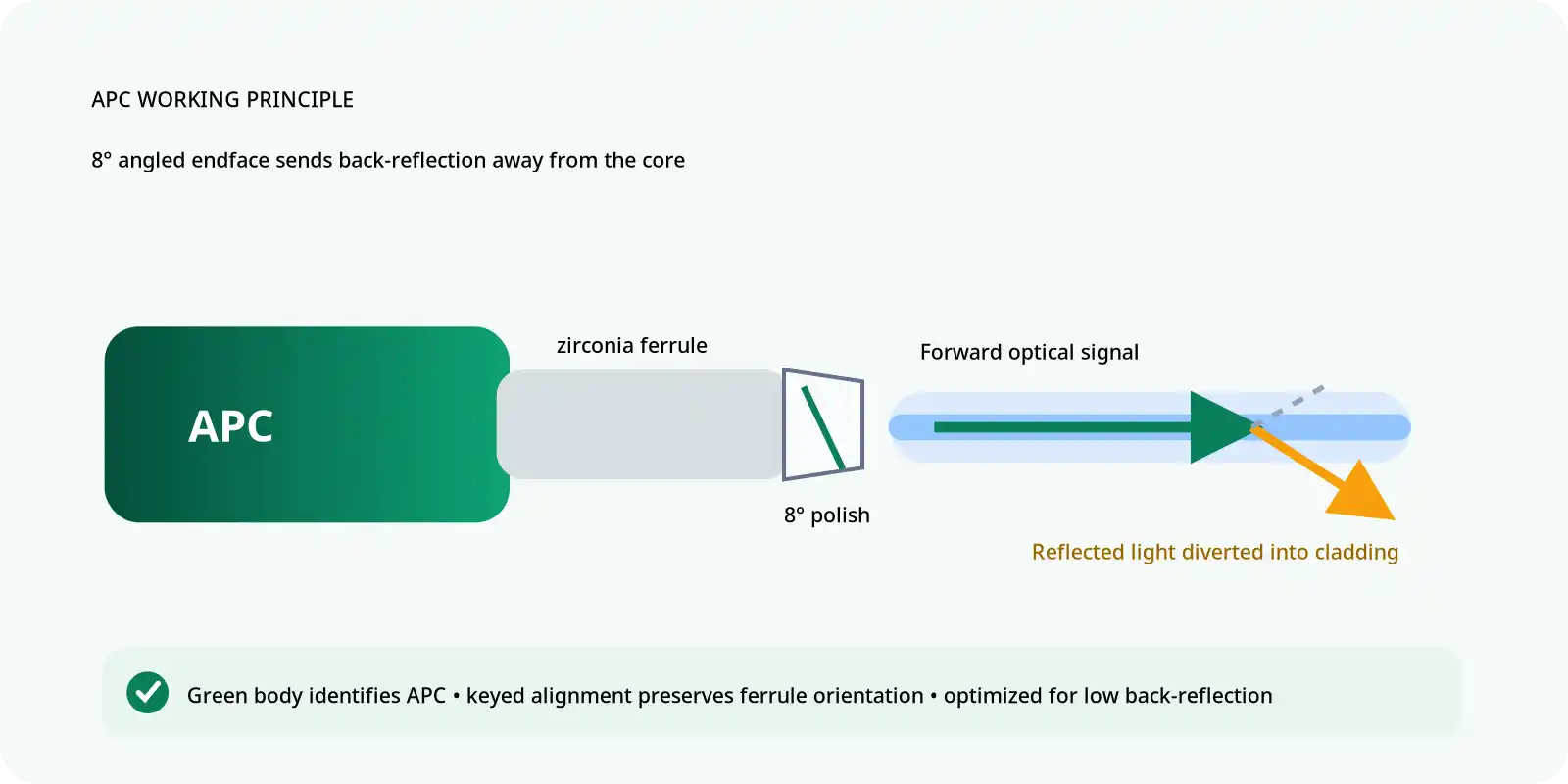
APC interfaces are widely used when connector-generated reflection must be reduced. FOCC's guide to SC APC vs SC UPC connector polish explains why an angled physical-contact interface redirects reflected energy differently from a straight UPC interface.
Connector condition matters as well as connector type. If the system uses removable interfaces, the available fiber optic connector options should be specified together with the required polish, fiber type, and mating interface rather than treating "FC," "SC," or "LC" as a complete optical-reflection specification.
Reflective Components and Samples
Fiber Bragg gratings, mirrors, reflective sensors, filters, test targets, and workpieces can intentionally return light. In these systems, the reflected signal may be useful somewhere else in the optical path but still undesirable at the source.
Back Reflection vs Backscatter
Back reflection and distributed backscatter are related sources of reverse-traveling power but are not the same physical phenomenon. A discrete interface may produce a comparatively localized reflection, while scattering can be distributed along a fiber or optical path. From the isolator's perspective, the system-level issue is how much reverse optical energy can reach the protected source.

Why Optical Feedback Can Disturb Lasers and Amplifiers
A laser cavity can respond to light that re-enters through the output path. The effect depends on the laser architecture, returned power, coherence, spectral relationship, and operating conditions. Optical feedback may contribute to output noise, power fluctuation, spectral instability, or other unwanted behavior. In some high-power systems, sufficiently strong back-reflected power can also create a damage risk.
Amplifier stages also need to be evaluated as part of the complete optical chain rather than as isolated components. FOCC's optical amplifier guide provides additional background on amplifier architectures and the role of optical isolation within amplified systems.
How a Faraday Optical Isolator Works
A conventional Faraday isolator relies on non-reciprocal magneto-optic rotation. In a simplified polarization-dependent design, the forward optical field passes through a polarization-selective element, undergoes Faraday rotation, and reaches an output polarization state that is transmitted by the next optical element.
When light returns from the opposite direction, the Faraday rotation does not simply reverse the forward transformation. The returned polarization reaches the input-side optical structure in a state that is rejected or redirected. The physical implementation of polarization-independent and PM fiber isolators can be more complex, but the system-level result is the same: forward transmission is favored while reverse transmission is suppressed.
Isolation, Insertion Loss, and Return Loss Are Not the Same
| Parameter | What It Describes | Preferred Direction |
|---|---|---|
| Insertion loss | Forward optical power lost while passing through the isolator | Lower |
| Isolation | Suppression of optical power propagating in the reverse direction | Higher |
| Return loss | Ratio describing how little optical power is reflected back from a device or interface | Higher |
These values describe different optical behaviors. A device may provide strong reverse isolation while its connector interfaces still require careful return-loss control. Conversely, a low-reflection APC connection does not create the directional blocking function of an isolator.
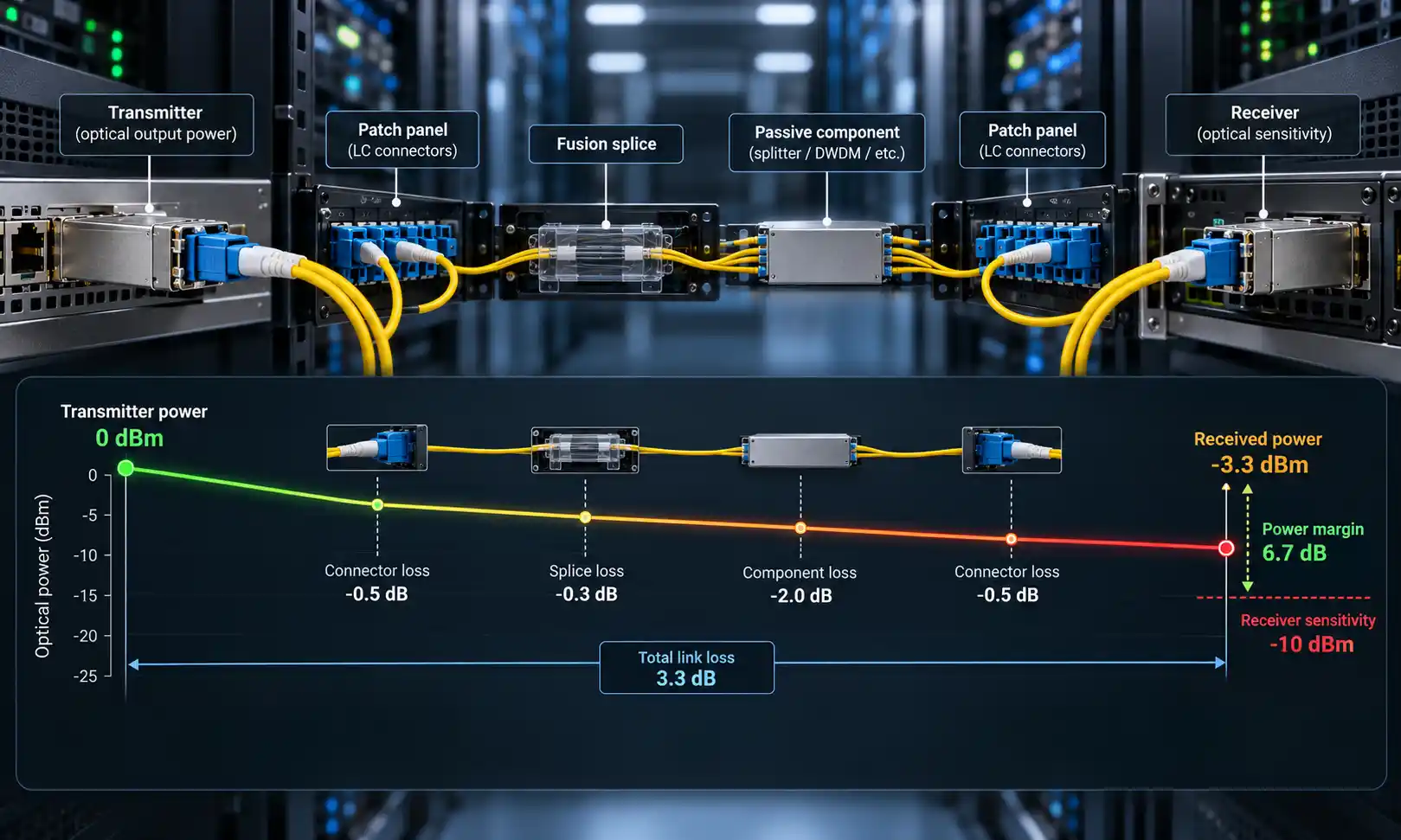
For production or incoming inspection, these measurements should also be treated separately. IEC 61300-3-4:2023 describes methods for attenuation measurement, while IEC 61300-3-6:2008 covers return-loss measurement of a fibre optic device under test. IEC 61300-3-4:2023 and IEC 61300-3-6:2008 are useful reference points.
FOCC's single-channel insertion-loss tester and insertion-loss and return-loss test equipment illustrate why ordinary transmission loss and reflected-power measurements are treated as different test functions.

Can an APC Connector Replace an Optical Isolator?
No. They solve different parts of the same reflection-control problem.
| Component | Main Role |
|---|---|
| APC connector | Reduces the amount of reflection coupled directly back from a specific connector interface |
| Optical isolator | Attenuates reverse-traveling optical power returning from the downstream system |
A reflection-sensitive system may use both. APC interfaces can reduce reflection at connection points, while an isolator positioned near a sensitive laser can reduce reverse power returning from many downstream sources.
This also means that replacing UPC with APC should not automatically be presented as an alternative to optical isolation. For PM systems in which reflected power is especially important, FOCC also lists AR-coated PM patch cables, which address interface and transmission requirements rather than replacing the isolator's directional function.

Polarization-Independent vs PM Fiber Isolators
The phrase "fiber optic isolator" is not a complete procurement specification. The polarization architecture of the source and downstream system determines which class of device is appropriate.
Polarization-Independent Isolators
In ordinary single-mode fiber links, the input state of polarization can vary with bending, stress, temperature, and other conditions. A polarization-independent isolator is intended to provide the specified isolation function without requiring one fixed launch polarization.
IEC 61753-061-2:2020 specifies minimum test and measurement requirements for single-mode pigtailed polarization-independent isolators for Category C controlled environments. A 2025 corrigendum has also been issued for this standard. IEC 61753-061-2:2020 is therefore a more appropriate reference than treating generic product claims as a standard.
For this type of device, polarization-dependent loss (PDL) is one of the relevant performance parameters. IEC 61300-3-2:2009 defines measurement methods for determining how the loss of a single-mode passive component changes with polarization. IEC 61300-3-2:2009 explicitly includes isolators among the passive devices to which the method can apply.
PM Fiber Isolators
A polarization-maintaining system has a different requirement. The optical path may need to preserve a defined slow or fast axis, so the isolator must be considered together with PM fiber type, axis orientation, connector keying, splice rotation, launch polarization, and polarization extinction ratio.
FOCC's introduction to polarization-maintaining fiber provides the underlying fiber context, while the PM fiber patch cable selection guide addresses connector and interface choices.
For PM passive components, IEC 61300-3-55:2020 provides methods for measuring PER and connector keying accuracy. IEC 61300-3-55:2020 also covers detection of principal-axis orientation, which makes it directly relevant to PM component verification.
FOCC's polarization extinction ratio tester and polarization-maintaining device testing pages provide related in-house product and test context.
Where Should an Optical Isolator Be Placed?
The isolator should be positioned to protect the component that is sensitive to reverse optical feedback. A common arrangement is:
Laser → Isolator → Downstream Fiber System
Placing the isolator close to the protected source limits the downstream optical path that reverse light can travel before encountering the isolation stage. Coherent describes Faraday isolators as commonly being used at laser or amplifier outputs for this purpose.
More complex systems may contain several gain stages or reflective paths, so the correct placement should come from the actual optical diagram rather than from a fixed rule copied from another laser.
Before selecting the location, identify:
- the reflection-sensitive source or gain stage;
- intentional reflective elements such as FBGs or samples;
- connectors and splices;
- the required forward signal path;
- every credible reverse path; and
- where returned light is useful versus where it should be suppressed.
The isolator is directional. During installation, follow the manufacturer's input/output labels or directional arrow. Do not infer operating direction from FC, SC, LC, APC, or UPC connector style.
Optical Isolator vs Optical Circulator
| Device | What Happens to Reverse Light? | Typical Decision |
|---|---|---|
| Optical isolator | Strongly attenuated | Use when returned light should not reach the source and does not need to be recovered |
| Optical circulator | Redirected to another port | Use when the returned signal is useful for sensing, detection, reflection measurement, or another optical path |
FOCC's optical circulator overview explains the routing concept, while the company's polarization-maintaining optical circulator is relevant when the returned signal must also preserve a defined polarization axis.
How to Select a Fiber Optic Isolator
A practical isolator specification starts with the protected source, not with a catalog headline such as "1550 nm" or "high isolation."
| Parameter | Question to Answer | Why It Matters |
|---|---|---|
| Source type | Laser, amplifier, SLD, ASE source, or another source? | Feedback sensitivity and spectral behavior differ by source architecture |
| Wavelength and bandwidth | What is the full operating spectrum, not only the nominal center wavelength? | Isolation and insertion loss are wavelength dependent |
| Required isolation | How much reverse power must be removed before it reaches the source? | Isolation must meet the source's feedback requirement rather than an arbitrary maximum |
| Insertion-loss budget | How much forward loss can the system accept? | The isolator consumes part of the optical power budget |
| Polarization | PI, polarizing, or PM architecture? | Determines whether PDL, PER, axis orientation, or connector keying matters |
| Fiber and connector | SMF or PMF? APC or UPC? What pigtail and connector key? | Interfaces must match the rest of the optical system |
| Optical power | What continuous and, where relevant, peak power reaches the isolator? | Power handling is a separate design requirement from isolation |
| Environment | What operating and storage conditions are required? | Typical room-temperature data should not automatically be treated as guaranteed limits |
| Acceptance evidence | Which parameters require factory or incoming verification? | Volume procurement should be based on guaranteed limits and test evidence |
Estimating the Isolation Requirement
If the downstream returned optical power can be estimated and the source manufacturer specifies a maximum permissible feedback level, the difference between those two levels establishes the minimum reverse suppression needed before any project-specific engineering margin is applied.
For example, the workflow is:
- Estimate or measure the worst credible reverse power at the isolator output side.
- Find the source's allowable feedback limit from the source or system specification.
- Determine how much attenuation is required to bring the returned power below that limit.
- Check that the selected isolator meets that isolation requirement over the complete wavelength, power, polarization, and temperature range that matters.
- Confirm that its forward insertion loss still fits the optical budget.
This approach is more meaningful than selecting the highest available isolation number without considering the actual source.
How to Verify a Fiber Optic Isolator
| Parameter | What the Test Proves | Important Check |
|---|---|---|
| Forward insertion loss | How much useful signal is lost through the intended direction | Measure at the specified wavelength and launch condition |
| Reverse isolation | How strongly backward transmission is suppressed | The measurement system must have sufficient dynamic range for the expected isolation |
| Return loss | How much power is reflected by the device or interface | Do not infer return loss from reverse-isolation data |
| PDL | How loss changes with polarization in a PI device | Relevant to polarization-independent single-mode components |
| PER and axis/key accuracy | How well a PM component preserves the intended polarization relationship | Relevant to PM fiber, connector keying, and axis alignment |
| Environmental verification | Whether performance remains within guaranteed limits under required conditions | Compare guaranteed values, not only room-temperature typical values |
IEC provides separate standardized methods for several of these measurements: attenuation, return loss, PDL, and PER and keying accuracy.
Common Fiber Isolator Selection Mistakes
| Mistake | Why It Creates Risk |
|---|---|
| Buying by wavelength alone | Isolation, bandwidth, polarization, power, and connector requirements may not match |
| Treating return loss and isolation as the same parameter | They describe different optical paths and different failure mechanisms |
| Assuming APC replaces an isolator | APC reduces a specific interface reflection but does not suppress every downstream reverse signal |
| Ignoring insertion loss | The isolator consumes part of the forward optical budget |
| Installing the device backwards | The isolator is directional |
| Using a PM isolator without defining axis requirements | PM performance depends on correct launch, keying, splicing, and axis alignment |
| Using typical values as guaranteed limits | Production design needs limits over the actual operating range |
| Testing only forward power | Reverse suppression and reflected-power behavior remain unverified |
FAQ
Q: Does a fiber optic isolator eliminate all back reflections?
A: No. Reflections can still be generated downstream. The isolator reduces the amount of reverse-traveling optical power that reaches the protected source.
Q: Is optical isolation the same as return loss?
A: No. Isolation describes suppression of reverse transmission through the device. Return loss describes reflected optical power at an interface or device port.
Q: Can an APC connector replace an optical isolator?
A: No. APC controls reflection at a connector interface; an isolator suppresses reverse power returning from the downstream system. Reflection-sensitive systems may use both.
Q: Should the isolator be installed before or after a laser?
A: For source protection, a common arrangement places the isolator after the laser output so returned light encounters the isolator before re-entering the source. Multi-stage laser and amplifier systems require placement based on the complete optical architecture.
Q: Does every PM system need a PM isolator?
A: No. A PM isolator is appropriate when the optical architecture requires preservation of a defined polarization axis. The complete source, fiber, splice, connector, and downstream component requirements determine the answer.
Q: Does higher isolation always mean a better isolator?
A: No. Wavelength range, forward loss, return loss, polarization performance, optical power, fiber interfaces, environment, and guaranteed test limits must all fit the application.
Final Selection Checklist
- Source type and feedback sensitivity
- Operating wavelength and complete bandwidth
- Required reverse isolation
- Maximum acceptable insertion loss
- Required return loss
- Polarization-independent, polarizing, or PM architecture
- Maximum PDL or minimum PER, where applicable
- PM axis and connector-key requirements
- Fiber type and pigtail construction
- Connector type and APC/UPC polish
- Continuous and peak optical power limits
- Operating and storage environment
- Factory or incoming-test requirements
Back-reflection control is a system problem rather than a single-component problem. Clean and correctly polished interfaces, APC connections where appropriate, optical isolators, and circulators each perform different functions.
The isolator's role is specific: allow the required forward signal to pass while reducing enough reverse optical power to protect the source under the actual wavelength, power, polarization, and environmental conditions of the system.
For PM interfaces or low-reflection interconnects, FOCC's PM FC/APC patch cables provide another relevant system component. If the required isolator configuration or related optical path is not a standard arrangement, provide the wavelength, bandwidth, source type, optical power, required isolation, fiber type, polarization requirement, connector polish, operating environment, and test requirements through the FOCC inquiry page.