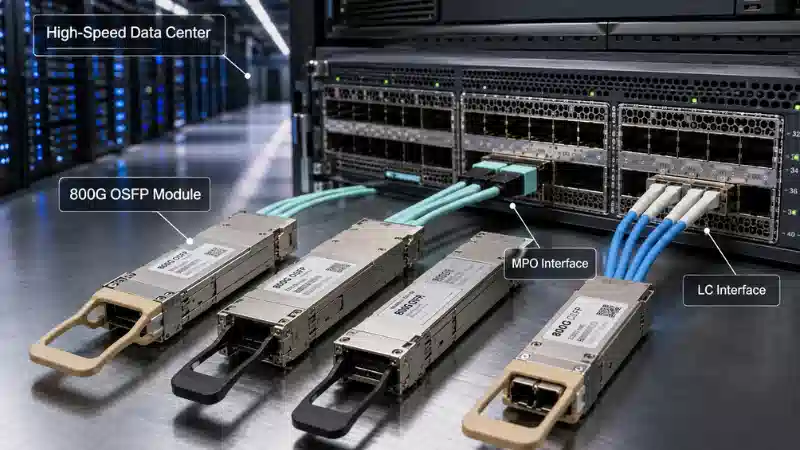
An MTP breakout cable converts a single high-density MTP connector into multiple individual duplex connectors, typically LC or SC. This design allows one multi-fiber port on network equipment to connect to several separate devices or ports, each requiring a standard two-fiber connection. The breakout happens through a protective housing that splits the fibers from the MTP connector into individual tails, each terminated with its own duplex connector.

How MTP Breakout Cables Work
The fundamental architecture of an mtp breakout involves three main components. At one end sits the MTP connector, which can house 8, 12, 16, 24, or even 32 individual fibers within a single ferrule. These fibers travel through the main cable body until they reach the breakout point, where a protective housing separates them into individual fiber strands. Each strand then continues to its own duplex connector, creating multiple independent connection points from a single source.
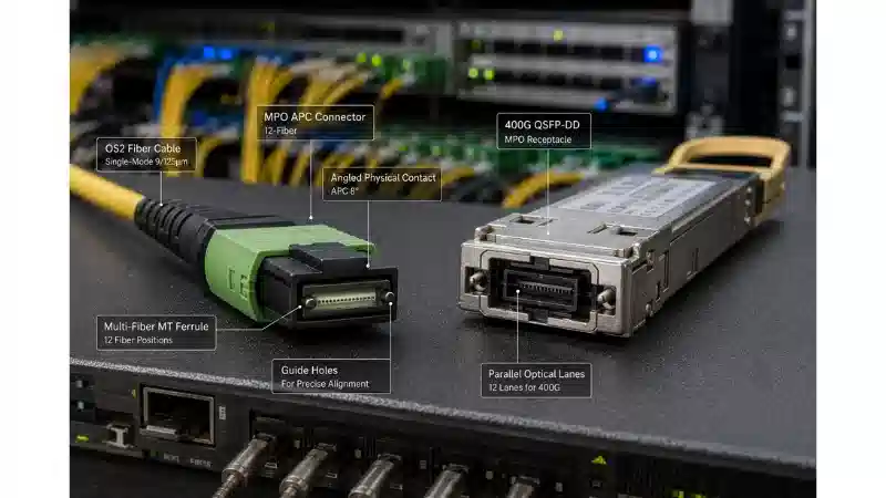
The MTP connector uses a multi-fiber push-on design that enables fast, secure connections while maintaining precise fiber alignment through guide pins and springs. When you plug an MTP connector into a compatible port, all fibers make contact simultaneously, establishing multiple optical pathways in one action. This parallel transmission capability forms the backbone of modern high-speed networking.
The breakout section serves as the transition zone between high-density and individual connectivity. Manufacturers typically use fanout lengths ranging from 0.5 to 2 meters, with protective tubing surrounding each fiber tail to prevent damage during installation and operation. The most common configuration is a 12-fiber MTP to 6 LC duplex breakout, though 8-fiber to 4 LC duplex versions have gained traction for specific applications.
Fiber Mapping in Standard Configurations:
8-fiber breakout: 4 duplex LC connectors (4 transmit fibers + 4 receive fibers)
12-fiber breakout: 6 duplex LC connectors (standard for 40G applications)
24-fiber breakout: 12 duplex LC connectors (high-density deployments)
The physical separation of fibers at the breakout point requires careful strain relief design. Without proper protection, the individual fiber tails become vulnerable to bending stress and physical damage. Quality MTP Breakout Cable assemblies incorporate rigid breakout housings made from hard plastic or metal, which anchor the fibers securely while allowing enough flexibility for routing to different connection points.
Primary Applications and Use Cases
Data centers represent the primary deployment environment for mtp breakout cables. These cables are especially well-suited for data centers where space constraints and complex cable management are common challenges, supporting data rates from 10G to 40G and 25G to 100G. The ability to split a single high-speed port into multiple lower-speed connections offers significant advantages in specific scenarios.
Network Speed Transitions
The most common application involves bridging different network generations. A 40G QSFP+ transceiver port can break out to four 10G SFP+ connections using an 8-fiber breakout cable. Similarly, a single-mode 8-fiber MTP to LC duplex breakout cable is specially optimized for 40G QSFP+ PSM4 to 10G SFP+ LR, and 100G QSFP28 PSM4 to 25G SFP28 LR optics breakout connections. This approach eliminates the need for expensive transceiver upgrades across an entire network during migration periods.
Consider a scenario where a core switch supports 100G connections but connects to older server racks running 25G interfaces. Rather than replacing all servers simultaneously, network engineers can deploy breakout cables that split each 100G port into four 25G connections. This strategy extends the useful life of existing infrastructure while enabling gradual migration to higher speeds.
Direct Device Connectivity
Breakout cables support applications where one high-speed MTP switch port connects to multiple lower-speed duplex switch or server ports, such as a single 100, 200, or 400 Gig switch port with an 8-fiber MTP interface breaking out to four duplex 25, 50, or 100 Gig server connections. This direct connectivity model reduces complexity by eliminating intermediate patch panels in certain configurations.
Storage area networks (SANs) frequently use breakout cables to connect high-density fiber channels. A single 24-fiber MTP connection from a storage controller can fan out to 12 separate server connections, each handling dedicated storage traffic. The parallel nature of the MTP connector ensures that all 12 connections maintain consistent latency and performance characteristics.
Structured Cabling Integration
While direct connections offer simplicity, many deployments integrate breakout cables into structured cabling systems. In structured cabling environments, breakout cables can be used as equipment cords in conjunction with MTP trunk cables and patch panels. This hybrid approach maintains the organization benefits of structured cabling while leveraging the flexibility of breakout cables at the equipment interface.
A typical implementation might use MTP trunk cables for permanent links between patch panels in different rows, then deploy breakout cables from patch panels to individual servers or switches. This architecture concentrates high fiber counts in the backbone while distributing connections at the edge, optimizing both density and accessibility.
MTP vs MPO: Understanding the Terminology
The terms MTP and MPO appear interchangeably in discussions about breakout cables, but they have distinct origins. MPO stands for Multi-Fiber Push-On, which is the generic industry standard for multi-fiber connectors. MTP is a registered trademark of US Conec and is an optimized version of the MPO connector, featuring enhanced mechanical and optical performance specifications.
From a practical standpoint, MTP connectors incorporate several improvements over generic MPO designs. The floating ferrule in MTP connectors uses tighter manufacturing tolerances, resulting in better fiber alignment and lower insertion loss. US Conec MTP connectors have a very low manufactured tolerance and a high spring force which ensures continued performance over time. This reliability matters significantly in production environments where fiber connections must maintain performance over years of operation.
However, both connector types maintain complete compatibility. An MTP breakout cable will mate properly with generic MPO ports, and vice versa. Network designers often specify MTP branded connectors for mission-critical applications where performance consistency justifies the marginal cost premium, while generic MPO connectors suffice for less demanding deployments.
The MT ferrule forms the core of both connector types, housing the individual fiber ends in a precisely molded plastic component. When two MT ferrules meet in a mating adapter, guide pins ensure perfect alignment, allowing light to pass between fibers with minimal loss. This standardized ferrule design enables the broad interoperability that has made multi-fiber connectors successful in the market.
Key Technical Specifications
Fiber Count and Configurations
MTP breakout cables come in several standard fiber counts, each serving specific network architectures. The 8-fiber version has emerged as a popular choice for newer deployments. Many users utilize an MPO-12 fiber for an MPO-8 application, where 4 strands transmit signal, 4 strands receive signal, and the middle 4 fiber lanes remain unused. This configuration aligns with the 4-lane parallel optics used in 40G and 100G transceivers.
Twelve-fiber breakouts represent the most established configuration, having been deployed widely since the introduction of 40G networking. Twenty-four fiber versions support ultra-high-density applications, though they require more sophisticated cable management due to the larger number of breakout tails. Some specialized applications use 16-fiber breakouts, which have become more popular for 200G SR8 or 400G SR8 utilization at one end with matching 25G SFP28 or 50G PAM SFP56 at the other end.
Polarity Management
Polarity refers to the fiber mapping between transmit and receive positions across a connection. For pre-terminated, high-density MTP cabling systems, fiber polarity issues must be addressed to ensure that a transmit signal from any type of active equipment will be directed to receive port of a second piece of active equipment. The TIA 568 standard defines three polarity methods-Type A, Type B, and Type C-each suited to different network architectures.
Type B polarity has become the preferred choice for parallel optics deployments. Type-B MTP cable uses key-up connectors on both ends, creating a "flipped" polarity that results in a Pin 1 to Pin 12 relationship. This configuration allows direct connection between QSFP transceivers without requiring polarity conversion in the middle of the link.
Type A polarity maintains straight-through fiber mapping but requires careful planning to ensure proper transmit-to-receive alignment. Many installations use Type A trunk cables with Type B patch cords to achieve correct polarity. Type C polarity implements pair-wise flipping, which works well for duplex storage applications but proves less common in modern parallel optics deployments.
Optical Performance
Insertion loss measures how much light signal degrades when passing through a connection. The conventional standard loss is less than 0.7dB, while low-loss Elite connectors achieve less than 0.35dB. This difference might seem minor, but in links with multiple connections, the cumulative loss budget determines maximum transmission distance and reliability.
Return loss indicates how much light reflects back toward the source rather than continuing through the connection. Higher return loss values (measured as positive dB numbers) indicate better performance, with typical specifications requiring greater than 20dB for multimode connections and greater than 30dB for singlemode. Poor return loss can cause transmitter instability and reduce overall link margin.
Fiber type selection depends on transmission distance and speed requirements. OS2 single-mode types suit scenarios requiring long-distance transmission, while multi-mode types such as OM3 and OM4 are more suitable for internal data centers and short-distance high-density connections. OM3 supports 40G up to 100 meters, OM4 extends that to 150 meters, while newer OM5 fiber enables shorter wavelength division multiplexing for increased capacity.

Installation and Design Considerations
Cable Management
The physical properties of breakout cables create unique cable management challenges. Unlike trunk cables that maintain a single sheath throughout their length, breakout cables transition from one thick cable to multiple thin tails. This expansion requires planning to prevent congestion at the breakout point.
Installers typically secure the main cable body to cable trays or conduits, then route the individual breakout tails to their respective connection points. The OFNP plenum jacket is safe for plenum air spaces, meeting UL 910 regulations and compatible with both unrated and OFNR riser rated applications. Proper jacket rating selection ensures code compliance in different building spaces.
The breakout housing must be anchored securely to prevent strain on the individual fiber tails. Many designs include mounting ears or slots that allow zip-tie attachment to rack rails or cable managers. Without proper strain relief, the weight of the main cable can pull on the breakout section, potentially damaging fibers over time.
Connector Gender and Keying
MTP connectors come in male (with pins) and female (without pins) versions. Male connectors are WITH Guide Pins, while Female connectors are WITHOUT Guide Pins, and for Data Center Connections using 100G SR4 and 400G SR8, the connecting MTP cable must be FEMALE due to QSFP28 and QSFP-DD modules having a built-in male connector socket with guide pins.
The keying position-either "key up" or "key down"-determines the connector's orientation in the adapter. Key position affects polarity and must be consistent with the overall cabling system design. Most modern deployments standardize on key-up orientation for simplified installation and maintenance.
Testing and Verification
Factory terminated and tested assemblies deliver verified optical performance and reliability for improved network integrity. However, field verification remains important after installation. Optical loss testing using a power meter and light source confirms that each fiber path meets performance specifications.
Visual inspection catches physical damage that might not be apparent from loss measurements alone. Fiber end-face inspection with a microscope reveals contamination, scratches, or cracks that can degrade performance or cause complete link failure. It is essential to maintain clean fiber optic end faces, as even microscopic dust can degrade signal quality and reliability.
MTP Breakout vs MTP Trunk Cables
Understanding when to use breakout versus trunk cables involves analyzing your specific connectivity requirements. MTP trunk cables generally have identical MTP connectors on each end, while breakout cables have an MTP connector on one end and multiple LC or SC connectors on the other. This structural difference reflects their distinct purposes in network design.
Trunk cables excel at creating high-capacity backbone links. When you need to connect two patch panels or establish a permanent high-speed link between network equipment locations, trunk cables provide the most efficient solution. Trunk cables form the backbone highways, aggregating fibers across data center rows and between facilities. Their identical end connectors enable straightforward connection planning and consistent polarity management.
Breakout cables shine in situations requiring flexibility at the device level. If you need to split high-speed ports into multiple low-speed ports to connect multiple servers or storage devices, improve port utilization, and flexibly respond to different device access requirements, you should choose MTP breakout cables. They provide the last-mile flexibility that trunk cables cannot match.
Cost considerations also play a role. Trunk cable installations using structured cabling methodology typically cost less per fiber than breakout cable deployments, since the trunk runs require less labor and materials. However, breakout cables eliminate the need for patch panels and cassettes in direct-connect scenarios, potentially reducing overall system cost in smaller deployments.
Many installations use both cable types strategically. The backbone infrastructure uses trunk cables for efficiency and future-proofing, while breakout cables handle the distribution to end devices. This hybrid approach balances the benefits of each cable type while minimizing their respective limitations.
Common Deployment Scenarios
Server Rack Connections
A typical top-of-rack switch deployment illustrates practical breakout cable usage. The switch might feature eight 100G QSFP28 ports, each requiring connection to four servers with 25G SFP28 interfaces. Rather than using 32 separate fiber pairs, eight 8-fiber breakout cables provide all required connections. Each cable plugs into one 100G port on the switch, then fans out to four servers, creating an organized star topology from the switch to the rack.
This configuration reduces cable congestion in vertical cable managers compared to running 32 individual duplex cables. The reduced cable count improves airflow through the rack, which benefits equipment cooling. Troubleshooting becomes simpler since each switch port's connections group together physically, making it easier to trace specific server connections.
Blade Server Integration
Blade server chassis present unique connectivity challenges due to their extremely high port density. A single chassis might house 16 server blades, each requiring at least one network connection. Using breakout cables from the blade chassis switch modules to external network infrastructure enables dense connectivity without overwhelming cable management systems.
The modular nature of blade systems means servers get added and removed regularly. Breakout cables accommodate this dynamic environment better than structured cabling approaches, since technicians can replace individual server connections without disturbing the main cable runs. The shorter breakout tail lengths (typically 0.5 to 1 meter) provide just enough reach within the blade chassis environment without excess cable length.
Migration Strategies
Network migrations rarely happen instantly across an entire infrastructure. Breakout cables enable gradual transitions by allowing new high-speed equipment to coexist with older lower-speed devices. A phased migration might start by installing a new 100G core switch while maintaining existing 10G distribution switches. Breakout cables from the core switch to distribution layer preserve the existing connectivity pattern during the transition period.
As budget and timing allow, older switches get replaced with higher-speed models. The breakout cables can be replaced with trunk cables to fully leverage the higher speeds, but the flexibility during the transition period reduces risk and minimizes downtime. This staged approach spreads capital expenditure over multiple budget cycles while maintaining operational continuity.
Frequently Asked Questions
What's the typical lifespan of an MTP breakout cable in production use?
Quality MTP breakout cables typically last 5-10 years in data center environments with proper handling. The actual lifespan depends heavily on mating cycle count-each time you connect and disconnect the MTP connector counts as one cycle. MTP connectors maintain high spring force which ensures continued performance over time, but repeated mating eventually degrades the ferrule and spring components. Most manufacturers specify 500-1000 mating cycles for their connectors. In practice, fixed installations that rarely get disconnected can exceed the rated lifespan, while frequently reconfigured connections may require earlier replacement.
Can you mix fiber types within a single MTP breakout cable?
No, all fibers within an MTP breakout must be the same type and grade. You cannot combine singlemode and multimode fibers in one cable, nor can you mix different multimode grades like OM3 and OM4. The fiber type specification applies to the entire assembly because the manufacturing process requires consistent fiber handling and testing procedures. If your application requires different fiber types, you need separate breakout cables for each type. This limitation actually simplifies network documentation and reduces the chance of accidentally connecting incompatible fiber types.
Why do some breakout cables cost significantly more than others?
Price variation in MTP breakout cables stems from several factors. Connector quality represents the largest cost differential-genuine US Conec MTP branded connectors cost more than generic MPO connectors but offer tighter tolerances and better long-term reliability. The lower the insertion loss, the more expensive the MPO breakout cable price is, with Elite low-loss versions costing more than standard-loss alternatives. Fiber quality also impacts price, with premium Corning or OFS fiber commanding higher prices than commodity alternatives. Finally, jacket ratings affect cost-plenum-rated cables cost more than riser-rated versions due to the specialized materials required for fire safety compliance.
Do I need special tools to install MTP breakout cables?
Basic installation requires only standard fiber optic handling practices-no specialized tools necessary. However, proper cleaning equipment is essential. Cleaning optical connectors are paramount in providing reliable, high-performance fiber optic connections. You'll need MTP-specific cleaning tools since the multi-fiber connector requires different cleaning techniques than duplex LC connectors. Optical inspection microscopes help verify cleanliness before mating connections. For testing, an optical loss test set (OLTS) with MTP launch cable adapters enables certification of the installed links. While these tools represent an investment, they're not breakout-cable-specific-you'd need them for any professional fiber optic installation.
Choosing between direct breakout connections and structured cabling with trunk cables depends on your network's scale, growth plans, and operational model. Small to medium deployments with relatively stable configurations often benefit from the simplicity of breakout cables connecting directly to equipment. Larger environments with frequent moves and changes typically fare better with structured cabling that concentrates all permanent fiber in trunk cables, using breakout cables only as short equipment cords where needed. Network maturity matters too-newer deployments can standardize on a single polarity method and connector type, while networks with accumulated legacy infrastructure might need mixed approaches to accommodate existing equipment.
The fiber density achievable with mtp breakout technology continues improving as transceiver technology advances. Where 12-fiber connectors once supported only 40G, similar physical interfaces now handle 400G through improved electronics and optics. This trend toward higher speeds from similar fiber counts reduces the total amount of fiber infrastructure needed, though it places greater demands on optical performance and cleanliness. Regular maintenance of connector end faces becomes even more critical as signal rates increase and loss budgets tighten.
Documentation assumes heightened importance in MTP systems compared to traditional duplex cabling. The multiple fibers within each connector make visual tracing impractical-you must rely on labels and records to identify specific fiber paths. Implementing a consistent labeling scheme and maintaining accurate as-built documentation from the start prevents troubleshooting headaches later. Consider including polarity type, fiber count, and connector gender in your labeling conventions to provide technicians with essential information at a glance.