If you've spent any time poking around a modern data center-or even just reading about them-you've probably come across the term MPO. Short for Multi-Fiber Push On, these cables have become something of a backbone in high-density environments where space is tight and speed is everything. But what exactly makes them tick? And why do so many network engineers swear by them?
Let me try to break this down without getting too deep into the weeds.

The Basic Idea
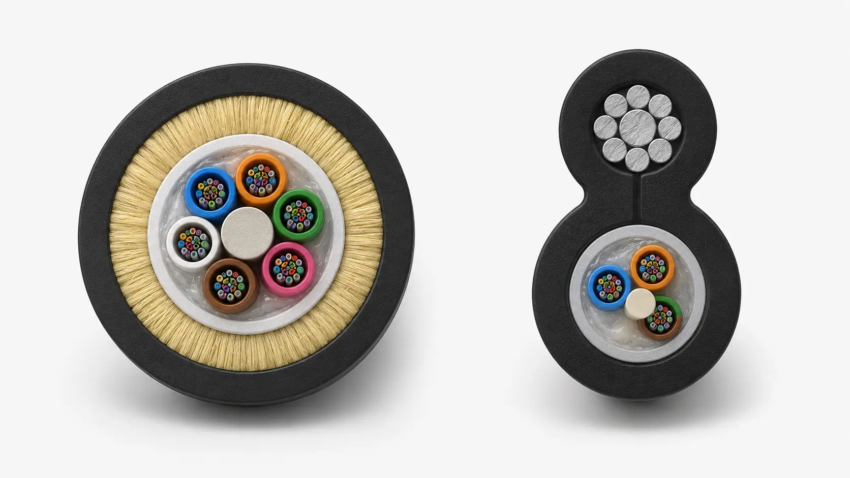
MPO cables bundle multiple optical fibers-usually 8, 12, or 24-into a single connector. That's the whole point, really. Instead of terminating each fiber individually (which is tedious, time-consuming work that requires skilled hands), you get a pre-terminated assembly that's ready to go. Plug and play, as they say.
The connector itself uses a rectangular ferrule with alignment pins. Male connectors have these little pins sticking out; female connectors have corresponding holes. Pretty straightforward once you see it. The pins ensure the fiber arrays line up precisely-critical when you're dealing with transmission at these scales.
Now, you'll often hear MTP mentioned in the same breath. MTP is actually a brand name from US Conec-it's their enhanced version of MPO. Better mechanical tolerances, improved spring mechanism, that sort of thing. The two are completely compatible. All MTPs are MPOs, but not all MPOs are MTPs. Kind of like how all bourbon is whiskey but not all whiskey is bourbon. If that helps.
Why Bother With All This?
Density. That's the short answer.
Data centers are constantly battling for space. Every square foot matters. When you can consolidate 12 or 24 fibers into a single connector the size of what used to carry two, you've just multiplied your capacity without expanding your footprint. The cable management alone is a revelation-ask anyone who's had to trace individual duplex cables through a crowded rack.
Installation time drops dramatically too. Factory-terminated cables mean less time on-site, fewer opportunities for human error, and (honestly) fewer headaches. I've talked to technicians who've cut their deployment time in half just by switching to MPO infrastructure.
The Fiber Count Question
This gets a bit more nuanced than people expect.
12-fiber MPO cables were the original workhorse. They're still everywhere. The thing is, parallel optics applications like 40GBASE-SR4 only use 8 fibers-4 for transmit, 4 for receive. So when you're running 12-fiber cables for 40G, you've got 4 fibers just sitting there doing nothing. Wasteful? Maybe. But 12-fiber became the standard before these applications existed, and infrastructure tends to outlast the technology it was built for.
8-fiber MPO cables came along precisely to address this. Same footprint, better utilization. For pure parallel optics deployments, they make more sense economically.
24-fiber and higher counts are for the heavy lifting-think 100G applications using CFP transceivers, or newer 400G deployments. There's even 16-fiber variants specifically designed for certain 400G interfaces. The landscape keeps evolving.

Trunk, Breakout, Conversion
MPO cables come in different flavors depending on what you need them to do.
Trunk cables have MPO connectors on both ends-same fiber count throughout. They form the permanent links in your infrastructure, running between patch panels or distribution areas. Think of them as the highways.
Breakout cables (also called harness or fanout cables) split that MPO connector into individual duplex connections-typically LC connectors. An MPO-to-4xLC breakout, for instance, lets you connect a single 40G transceiver to four separate 10G ports. Incredibly useful for migration scenarios.
Conversion cables transform between different MPO configurations. A 24-fiber to three 8-fiber conversion, say. These help you adapt existing infrastructure to new equipment without ripping everything out.
Polarity-The Thing Nobody Wants to Think About
Okay, here's where it gets a bit tedious. But stick with me because getting this wrong means your links simply won't work.
Polarity ensures that transmit on one end connects to receive on the other. Simple enough in concept. The TIA-568 standard defines three methods-A, B, and C-using corresponding cable types.
Type A is straight-through. Fiber position 1 on one end goes to position 1 on the other. Key up on one connector, key down on the other. The polarity flip happens in the patch cord.
Type B cables flip everything. Position 1 goes to position 12, position 2 to position 11, and so on. Both connectors are key up. This type is arguably the simplest for direct transceiver-to-transceiver connections because the cable itself handles the Tx/Rx flip.
Type C does a pair-wise flip-positions 1 and 2 swap, 3 and 4 swap, etc. Mostly used in specific duplex scenarios. Less common in modern parallel optics deployments.
The practical advice? Pick a method and stick with it throughout your facility. Mixing polarity types is a recipe for late-night troubleshooting sessions.

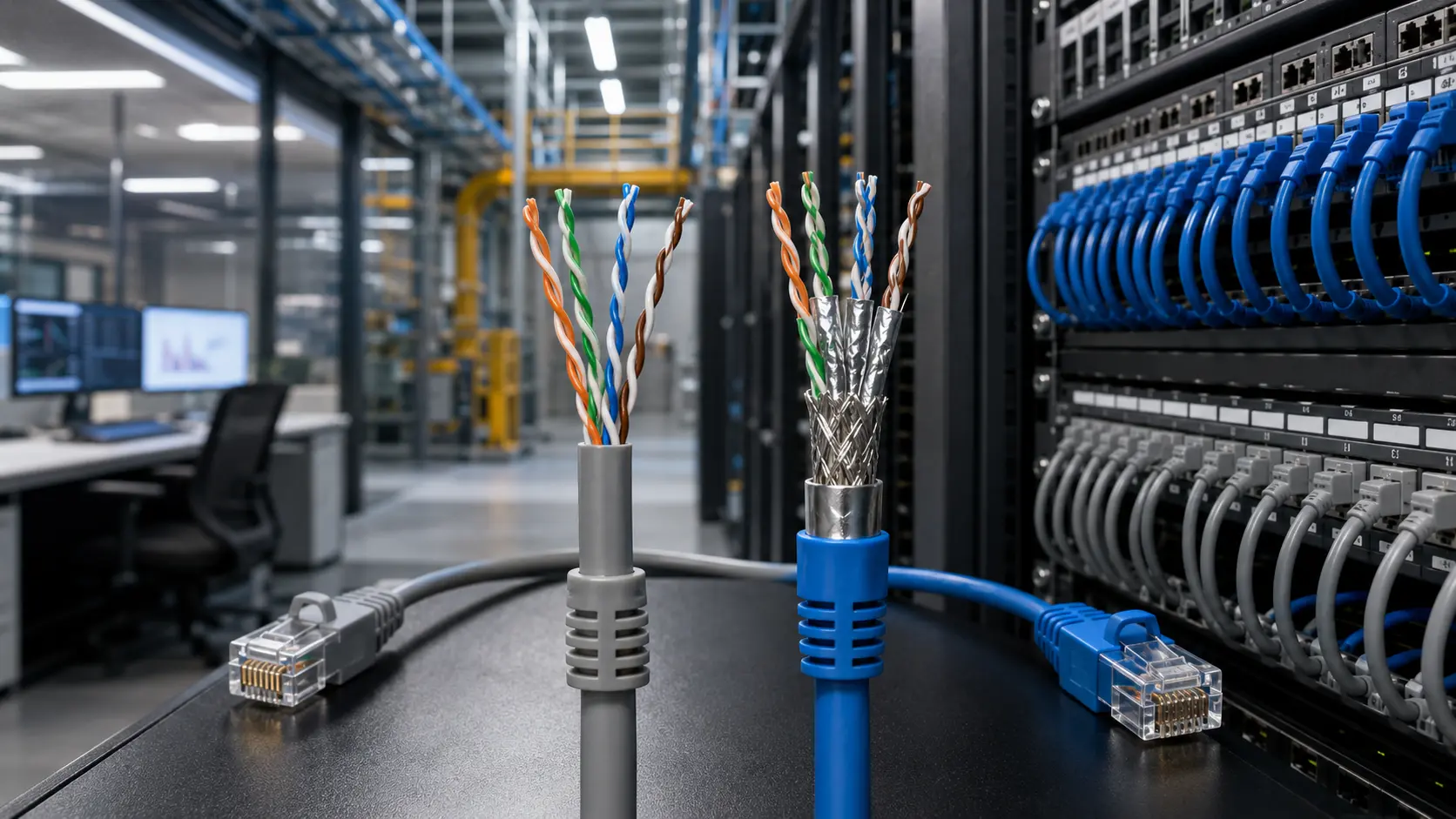
Single-Mode vs. Multimode
MPO cables work with both fiber types, though multimode dominates in short-reach data center applications.
Most deployments use OM3 or OM4 multimode fiber-aqua colored jackets, 50-micron cores optimized for VCSEL lasers. OM4 offers slightly better performance: 550 meters at 10G versus 300 for OM3. The price difference has narrowed enough that OM4 is often the default choice now.
OM5 is the newer kid on the block. Lime green jacket, designed specifically for wavelength division multiplexing applications-shortwave WDM, basically. It can carry multiple wavelengths simultaneously, which is how you get to 400G and beyond without increasing fiber count. Future-proofing for those thinking long-term.
Single-mode MPO shows up in longer reach applications or when absolute maximum bandwidth matters. Yellow jackets. Usually terminated with APC (angled physical contact) connectors to minimize back-reflections. More expensive, but necessary when multimode distances won't cut it.
The Cleaning Situation
This is where MPO cables demand more attention than people typically give them.
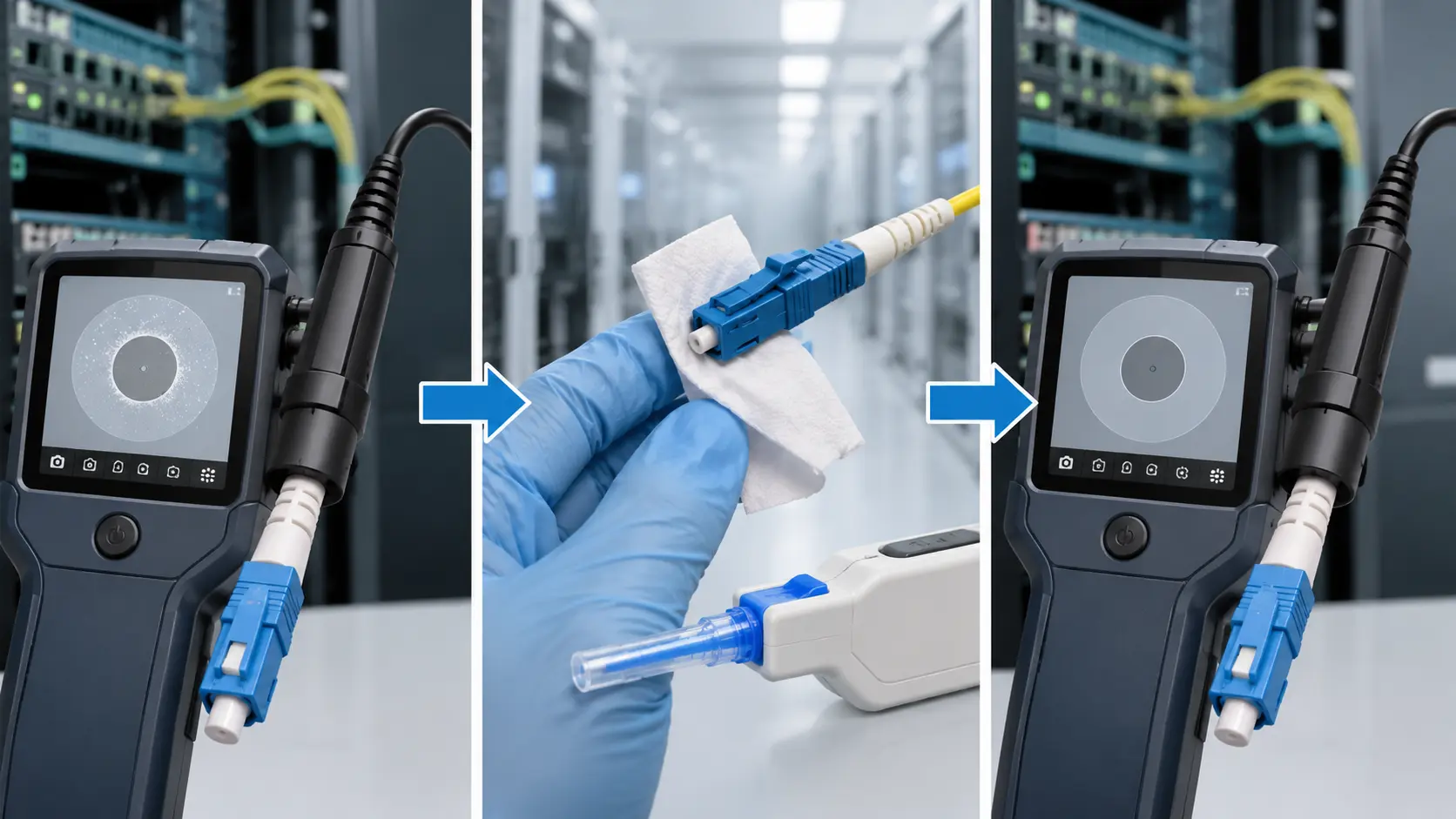
A contaminated connector on a duplex cable ruins one link. A contaminated MPO connector can take out 12 or 24 links at once. The stakes are higher. And because the fiber protrusion on MPO ferrules is measured in microns-typically 1 to 4-even tiny particles cause problems. A speck of dust that wouldn't matter elsewhere can prevent proper physical contact across multiple fibers.
The standard wisdom: inspect before you connect. Every time. Use a dedicated MPO inspection scope that can image the entire array. If cleaning is needed, dry methods first-lint-free wipes designed for MPO ferrules. Wet cleaning only if dry doesn't work, and always re-inspect afterward.
Don't forget the alignment pins on male connectors. Contamination there affects mating geometry for every fiber in the array.

Speed Roadmap
MPO cables have scaled remarkably well with network speed demands.
At 40G (SR4), you're using 8 fibers with 10G per lane. Straightforward.
100G (SR4) bumps each lane to 25G, still on 8 fibers.
200G typically uses 8 fibers at 50G per lane, or doubles up with 16 fibers.
400G gets interesting. Options include 16 fibers at 50G per lane (SR8), 8 fibers at 100G per lane with PAM4 modulation (SR4.2), or various single-mode approaches for longer distances. The 16-fiber MPO connector-same external dimensions as 12-fiber but packed tighter-was developed specifically for these 400G applications.
800G is already here in leading-edge deployments, typically using 16 fibers with advanced modulation.
The pattern is clear: either more fibers, faster lanes, or smarter encoding. MPO infrastructure supports all these approaches.
Common Mistakes
I've seen a few patterns over the years:
Gender confusion. Transceiver ports are male (with pins). That means your patch cord going into the transceiver must be female. Get this backward and you risk damaging expensive optics.
Key orientation errors. MPO connectors must mate key-up to key-down (Type A) or key-up to key-up (Type B), depending on your polarity method. Force a wrong orientation and you'll damage the pins.
Mixing OM3 and OM4 without realizing it. Both have aqua jackets by default. Some manufacturers use violet for OM4, but not all. Check the cable markings, don't assume by color.
Skipping inspection. Seriously. Just don't.
Final Thoughts
MPO technology isn't particularly glamorous. It's infrastructure-the kind of thing that should work so well you forget it exists. But the shift from individual fiber terminations to these multi-fiber assemblies has fundamentally changed how high-density networks get built.
The advantages are real: faster deployments, better space utilization, cleaner cable management, and a clear upgrade path as speeds increase. The tradeoffs-polarity complexity, stricter cleanliness requirements, higher per-connector cost-are manageable with proper planning and discipline.
For anyone building or upgrading a data center, campus network, or any environment where bandwidth demands keep growing, MPO cables aren't just an option. They're increasingly the default expectation. The technology is mature, the ecosystem is robust, and the performance speaks for itself.
Just remember to clean your connectors.