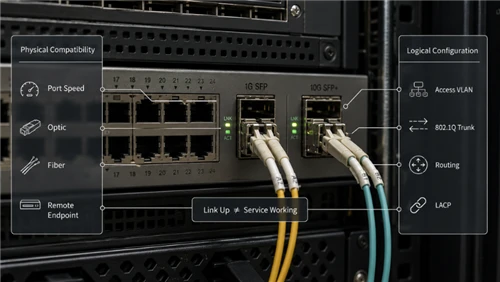
Configuring an SFP switch port requires two separate decisions. The physical decision covers port speed, module support, cabling, and the remote endpoint. The logical decision assigns the interface as an access port, VLAN trunk, routed port, or member of a Link Aggregation Control Protocol group.
A link can be physically up and still carry no useful traffic because the VLAN, native-VLAN, routing, or LACP settings are wrong. The reverse is also true: changing trunk commands cannot repair an unsupported speed, an incompatible optic, or a damaged fiber path.
This guide assumes that the basic transceiver standard has already been selected. For background on module functions, see what an SFP module does. For a focused explanation of form factors and speed compatibility, review SFP vs SFP+ compatibility.

Quick Answer: Use This Configuration Order
- Record the switch model, software release, physical port, current configuration, and remote endpoint.
- Determine whether the port is fixed at 1G, fixed at 10G, dual-rate, part of a shared speed group, or paired with a combo RJ45 interface.
- Confirm that the installed module, cable, and remote port support the intended Ethernet standard.
- Bring up and verify the physical interface before changing VLAN, routing, or LACP settings.
- Assign the logical role: access, trunk, routed, or aggregated.
- Verify the result at the physical, Layer 2, and Layer 3 or application layers.
- Save the configuration, record the optical baseline, and preserve a rollback path.
Do not copy a speed command from another switch family. Juniper's official EX Series port-speed guide shows that supported rates, interface names, automatic detection, and port-group requirements vary by model and port.
1G and 10G SFP Port Configuration Compared
| Configuration item | 1G SFP port | 10G SFP+ port |
|---|---|---|
| Typical optical standards | 1000BASE-SX, LX/LH, BX, EX, or ZX | 10GBASE-SR, LR, ER, ZR, or supported BiDi variants |
| Normal line rate | 1 Gigabit Ethernet | 10 Gigabit Ethernet |
| Lower-rate behavior | Some copper SFPs support additional negotiated rates; optical behavior is platform and module specific | A 1G SFP works only when the exact port, software, and module combination supports 1G mode |
| Common interface name | Often GigabitEthernet or ge | Often TenGigabitEthernet or xe |
| Typical short-reach fiber | 1000BASE-SX SFP over approved multimode fiber | 10GBASE-SR SFP+ over a qualified multimode channel |
| Typical single-mode option | 1000BASE-LX/LH SFP | 10GBASE-LR SFP+ |
| Main migration risk | Port or module may not support the future 10G mode | Existing fiber, remote port, optics, and port group must all support the planned 10G link |
These are starting patterns, not universal port rules. Similar cages do not prove identical host electrical interfaces or software support.
Identify the Port Before Entering Commands

Fixed-Rate SFP and SFP+ Ports
A fixed 1G SFP port cannot provide 10G service merely because an SFP+ module fits into the cage. A fixed 10G SFP+ port may reject a 1G module or leave the interface down unless lower-rate operation is explicitly supported.
The switch data sheet and compatibility information should answer four questions:
- Which rates does this exact physical port support?
- Does support depend on the software release?
- Does the port accept the selected module coding and power class?
- Does changing the speed affect neighboring ports?
When module recognition is uncertain, use the switch manufacturer's official compatibility tool. Cisco provides its transceiver module compatibility matrix for supported device and optic combinations.
Dual-Rate and Port-Group Designs
A dual-rate port supports more than one line rate, but the selection method can differ. The port may detect the inserted module automatically, require an interface command, require a chassis-level setting, or share one speed mode with several neighboring ports.
Use this decision process before trying to run a 1G SFP in a 10G cage:
- Find the exact physical-port specification. If it does not list 1G, stop; configuration cannot add unsupported hardware capability.
- Check software support. A hardware port may require a minimum release or a specific feature set.
- Check the port group. Some switches apply one rate to a group of interfaces, so changing one port can affect others.
- Check interface naming. A port may appear as a Gigabit interface in 1G mode and a Ten-Gigabit interface in 10G mode.
- Check the exact module. Support for one 1G optic does not prove support for every optical or copper SFP.
- Match the far end. Both endpoints must use compatible Ethernet standards and rates.
Cisco's official Gigabit Ethernet SFP data sheet includes product-specific 1G modules intended for supported higher-rate cages. That example does not mean every legacy SFP works in every SFP+ port.
Combo RJ45 and SFP Ports
A combo port has a copper connector and an SFP slot sharing one logical interface. Activating one side can disable the other. Before troubleshooting a dark SFP slot, confirm whether the paired RJ45 interface is active and whether the platform requires a media-selection command.
Managed-Switch Requirements
Access, trunk, routed-port, LACP, monitoring, and remote configuration features require a managed platform. The site's comparison of managed vs unmanaged switches provides additional context when the available device exposes only basic plug-and-play behavior.
Prepare a Rollback Record Before the Change
Capture the current state before replacing optics or changing the interface role:
- Switch model and software release
- Physical port and current interface name
- Running configuration for the interface and any port channel
- Installed module part number and detected type
- Current speed, administrative state, and operational state
- Access VLAN or trunk VLAN list
- LACP group and member state
- Digital Optical Monitoring baseline, if available
- Error counters and recent link events
- Remote device, port, module, and configuration owner
This record is both a troubleshooting baseline and a rollback package. It prevents a logical error from being confused with an optical fault.
Configure a 1G SFP Port
Verify the Physical Interface First
Install the supported module, enable the interface, and confirm that the switch identifies the optic. Verify the Ethernet standard at both ends, duplex-fiber polarity, connector cleanliness, and the remote transmitter.
For multimode links, the installed cable grade and channel length must match the selected standard. Existing or new channels may use OM3 multimode patch cords or OM4 multimode patch cords, but the complete installed channel-not the patch lead alone-sets the supported reach.
Illustrative Cisco IOS XE Access-Port Example
The following is an illustrative Cisco IOS XE pattern. Confirm the interface name, feature support, and syntax for the exact platform and release.
interface GigabitEthernet1/0/49
 description Building-A-Access-Link
 switchport mode access
 switchport access vlan 120
 no shutdown
An access port carries one untagged data VLAN unless another feature, such as a voice VLAN, changes the behavior. The VLAN must exist, and the remote endpoint must expect the same untagged network.
Illustrative Cisco IOS XE Trunk Example
interface GigabitEthernet1/0/49
 description Trunk-to-Access-Switch
 switchport mode trunk
 switchport trunk allowed vlan 10,20,30
 no shutdown
On the Catalyst platforms covered by Cisco's current IOS XE 17 interface guide, an access port carries one VLAN while a trunk can carry multiple VLANs using IEEE 802.1Q. The native VLAN handles untagged traffic, so both ends must use compatible tagging and native-VLAN behavior.
Configure a 10G SFP+ Port
Revalidate the Cable Before Reusing It
A cable that works at 1G is not automatically qualified for the chosen 10G standard. For 10GBASE-SR, confirm the installed multimode grade, length, connector condition, and total channel. For 10GBASE-LR, verify the single-mode path, total loss, and receiver limits. FOCC's older overview of 10 Gigabit Ethernet cabling options can be used as a starting point, while the actual optic data sheet remains the final reference.
Single-mode deployments commonly use OS2 single-mode patch cords between equipment and the installed channel. The complete route must still be inspected and tested.
Illustrative Cisco IOS XE 10G Trunk
interface TenGigabitEthernet1/1/1
 description Uplink-to-Distribution
 switchport mode trunk
 switchport trunk allowed vlan 10,20,30
 no shutdown
A physical link can remain up while one or more VLANs fail because the allowed list, native VLAN, or Spanning Tree state differs between endpoints.
Illustrative Cisco IOS XE Routed Port
interface TenGigabitEthernet1/1/2
 description Routed-Link-to-Core
 no switchport
 ip address 192.0.2.1 255.255.255.252
 no shutdown
A routed interface does not use access or trunk VLAN commands. Verify that the switch model and license support Layer 3 operation on the selected port.
Configure and Verify LACP
Link Aggregation Control Protocol, or LACP, combines compatible physical interfaces into one logical link. Member interfaces normally need matching speed, Layer 2 or Layer 3 mode, trunk behavior, VLAN settings, MTU, and other platform-defined attributes.
In LACP terminology:
- Active initiates negotiation by sending LACP packets.
- Passive responds but does not initiate.
- Active with active can form a channel.
- Active with passive can form a channel.
- Passive with passive does not initiate a channel.
-

Cisco's current IOS XE 17 EtherChannel guide also documents features such as minimum links, member compatibility, load-balancing, and monitoring commands.
Illustrative Cisco IOS XE LACP Trunk
interface range TenGigabitEthernet1/1/1-2
 description LACP-Members-to-Core
 channel-group 10 mode active
 no shutdown

interface Port-channel10
 description Aggregated-Trunk-to-Core
 switchport mode trunk
 switchport trunk allowed vlan 10,20,30
Apply the logical VLAN role consistently to the port channel and its members according to the platform's configuration model. A member that is physically up but not bundled may have a speed, VLAN, MTU, or LACP-partner mismatch.
LACP increases aggregate capacity across multiple flows and adds link redundancy. It does not guarantee that one flow uses the sum of all member speeds. The configured hashing policy normally keeps a given flow on one member.
Migrate from 1G to 10G With a Rollback Plan
A migration should be approved only after the switch ports, optics, fiber channel, remote endpoint, and application demand have been reviewed. The site's discussion of the business case for upgrading from 1G to 10G can help separate a real capacity requirement from an unnecessary hardware change.

Pre-Cutover Tasks
- Confirm both endpoints support the selected 10G mode and modules.
- Verify the installed fiber type, length, connector count, and target 10G standard.
- Save the current interface and port-channel configuration.
- Record link speed, DOM readings, error counters, VLAN reachability, routing adjacency, and representative application performance.
- Prepare the 10G modules or DACs at both ends.
- Keep the working 1G modules and old configuration available for rollback.
- Define success criteria and a maximum troubleshooting window.
Cutover Sequence
- Disable or isolate the affected service according to the change plan.
- Change the port or port-group speed mode if the platform requires it.
- Replace both endpoints with the planned 10G interfaces.
- Verify physical link, module recognition, and expected rate.
- Restore the access, trunk, routed, or LACP role.
- Repeat VLAN, routing, and application tests.
- Record the new DOM baseline and counters.
Rollback Triggers
Rollback should begin when any pre-agreed condition is met, such as:
- The physical link cannot be established within the change window.
- The port group change disrupts an unrelated interface.
- Required VLANs, routing adjacencies, or LACP members do not recover.
- Errors or link flaps increase after the change.
- The application acceptance test fails.
Rollback Sequence
- Remove the new 10G configuration and modules.
- Restore the original port or port-group mode.
- Reinstall the documented 1G modules.
- Restore the saved interface and LACP configuration.
- Verify the original physical, Layer 2, Layer 3, and application baselines.
- Preserve logs and observations for the next attempt.
Verify the Link With Evidence
| Layer | Evidence to collect | What it proves | What it does not prove |
|---|---|---|---|
| Physical | Module inventory, expected rate, link state, DOM, error counters, link-flap history | The host recognizes the interface and an optical or electrical link is established | Correct VLAN, routing, LACP, or application behavior |
| Layer 2 | Access or trunk state, allowed VLANs, native VLAN, MAC learning, STP state, port-channel membership | Frames can enter the intended broadcast domain and the logical link is forwarding | Correct IP routing or end-to-end application performance |
| Layer 3 | IP addressing, ARP or neighbor state, routes, gateway reachability, routing adjacency | The routed path is available | That the application or storage system can sustain the required workload |
| Application | Representative transfer, backup, storage, or service test | The change meets the operational requirement | Long-term reliability without monitoring |
Digital Optical Monitoring, or DOM, can report temperature, supply voltage, laser bias current, Tx power, and Rx power when the module and host support it. Cisco's official 10GBASE SFP+ data sheet documents these fields for supported products.
DOM values must be compared with the module's own thresholds and with the opposite endpoint. They are evidence about the physical layer, not proof that VLAN or routing configuration is correct.
Useful Cisco-Style Verification Commands
The following command families are illustrative. Syntax and availability vary by platform and release.
show interfaces status
show interfaces switchport
show interfaces trunk
show etherchannel summary
show lacp neighbor
show interfaces transceiver detail
For deeper guidance on interpreting the physical-layer evidence, use the site's procedure to troubleshoot a transceiver and switch port.
Evidence-Based Troubleshooting Matrix
| Symptom | Evidence to inspect | Likely cause | Next action |
|---|---|---|---|
| Module is not detected | Inventory, system log, EEPROM or unsupported-transceiver message | Unsupported coding, module seating, software, or damaged module | Check the compatibility matrix and test one known-supported module |
| Module is detected but link stays down | Configured speed, remote rate, Tx/Rx state, polarity, DOM | Fixed-rate mismatch, unsupported lower-rate mode, remote fault, or optical-path issue | Prove port-speed support before treating the fiber as the primary cause |
| Link is up but VLAN traffic fails | Switchport mode, allowed list, native VLAN, VLAN state, MAC table, STP | Tagging mismatch, missing VLAN, STP blocking, or incorrect access VLAN | Compare both endpoints and verify MAC learning in the intended VLAN |
| One LACP member is not bundled | Port-channel summary, LACP neighbor, member configuration, speed and MTU | Member mismatch, passive/passive pairing, remote configuration, or unsupported module | Compare the member against a working port and the logical port channel |
| Link flaps or CRC errors rise | Rx trend, temperature, error counters, event log, connector inspection | Marginal optical power, contamination, cable damage, heat, or unstable module | Clean and inspect the path, compare both ends, and change one component at a time |
| DOM looks healthy but service fails | VLAN, routing, LACP, ACL, and application test | The physical layer is probably not the primary fault | Continue at Layer 2 and Layer 3 rather than replacing the optic |
When a remote endpoint or installed fiber is difficult to isolate, a correctly matched loopback can help validate the local port and transceiver. Review fiber loopback selection before connecting one; the loopback must match the transceiver's fiber mode and interface.
FAQ
Q: Can every 10G SFP+ port run a 1G SFP?
A: No. The exact port, software, port-group mode, and module must support 1G operation. Physical fit alone is not evidence of compatibility.
Q: Should an inter-switch SFP link be an access port or a trunk?
A: Use access mode for one untagged VLAN and trunk mode for multiple VLANs. The term "uplink" describes a common role, not an automatic VLAN configuration.
Q: Does LACP turn two 1G links into one 2G connection?
A: It provides aggregate capacity across multiple flows and link redundancy. One flow normally remains on one member under the configured hashing policy.
Q: Should optical speed and duplex always be forced?
A: No. Follow the documentation for the exact switch, port, module, and remote endpoint. Optical and copper modules can have different negotiation behavior.