

Welcome to buy the 1×64 plc splitter module, sc/upc, g.657.a1 with our factory. As one of the leading manufacturers and suppliers in China, we also welcome the customized orders. Consult the price and the quotation with us now.
Specifications
| Configuration | Report-listed value |
|---|---|
| Part number | SPT-NP-1X64R-2M |
| Splitter configuration | 1×64 |
| Connector type | SC/UPC |
| Fiber type | G.657.A1 |
| Operating wavelength | 1260–1650 nm |
| Fiber length | ≥2.0 m |
| Package dimensions | 141 × 115 × 18 mm |
| Operating temperature | −40 to +85°C |
| Storage temperature | −40 to +85°C |
Confirm the input and output lead lengths, length tolerances and dimensional drawing when ordering. Allow additional installation space for connector access and fiber routing. The temperature ranges above are listed ratings; the supplied report contains optical results at three wavelengths, rather than environmental qualification results.
| Optical parameter | Report-listed requirement |
|---|---|
| Insertion loss | ≤20.40 dB |
| Polarization-dependent loss | ≤0.40 dB |
| Return loss | ≥50 dB |
| Output uniformity | ≤2.0 dB |
| Directivity | >55 dB |
64 Output Ports. Three Test Wavelengths.
The supplied inspection record lists insertion loss and polarization-dependent loss by output port, together with return-loss pass results, at 1310, 1490 and 1550 nm.
Sample S/N: 26070700094 · Inspection date: 7 July 2026
| Sample insertion-loss results | 1310 nm | 1490 nm | 1550 nm |
|---|---|---|---|
| Minimum insertion loss | 19.81 dB | 19.80 dB | 19.80 dB |
| Maximum insertion loss | 20.29 dB | 20.28 dB | 20.29 dB |
| Average insertion loss | 20.02 dB | 20.01 dB | 20.02 dB |
| Output uniformity | 0.48 dB | 0.48 dB | 0.49 dB |
The maximum insertion loss recorded at each test wavelength is below the report's 20.40 dB limit. Uniformity is the difference between the highest and lowest output loss at the same wavelength; this sample's recorded values range from 0.48 to 0.49 dB.
All 64 outputs are marked Pass for return loss at each of the three test wavelengths against the listed ≥50 dB requirement. The report records pass results, without numerical return-loss measurements for individual ports.
These results describe the identified sample. They do not establish production-wide typical values or replace the acceptance limits agreed for an order. The stated 1260–1650 nm operating range is broader than the three wavelengths measured in this record.
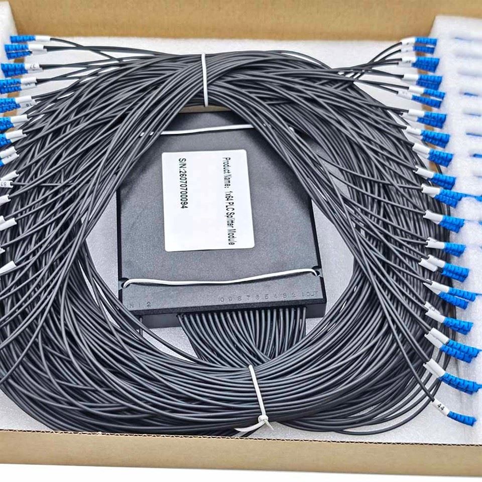
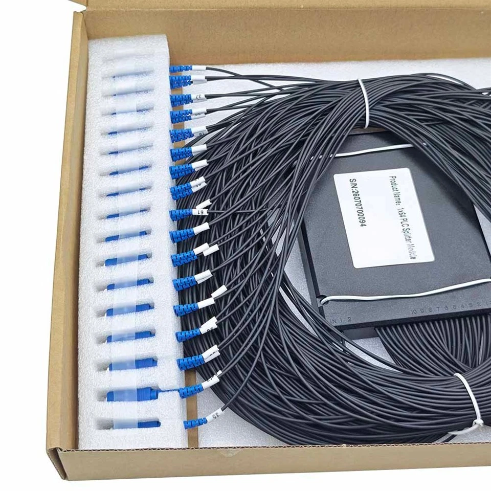
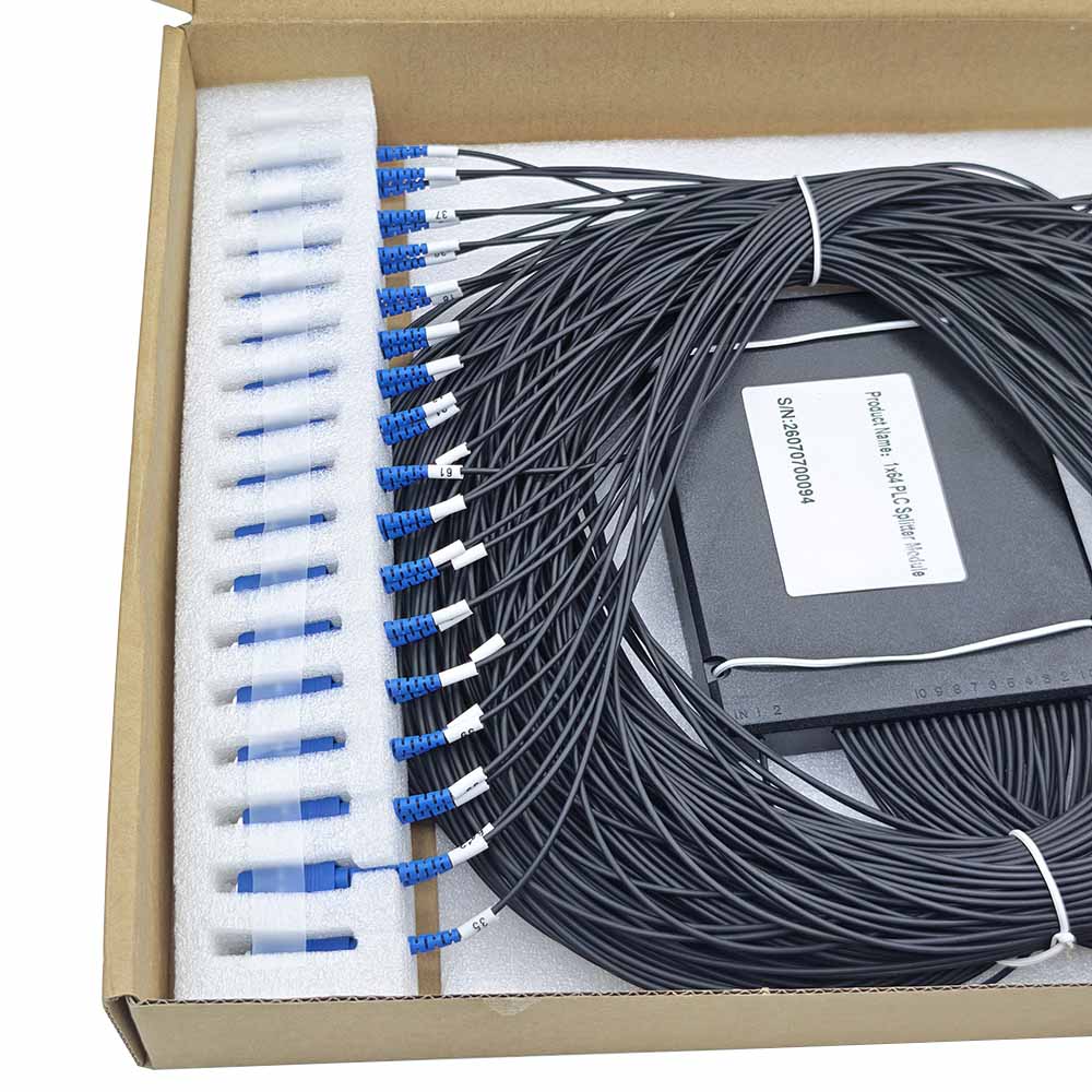
Numbered Leads for a 64-Branch InstallationWith 64 output paths to manage, clear branch identification matters during assembly, connection and later inspection. The product photographs show number labels on the output leads and a serial-number label on the module body. The inspection record is organized from Port 1 through Port 64.
Use the lead markings when establishing your installation's port schedule. Before connecting the module, check the input identification and output numbering against the assembly documentation, then retain that mapping with the network records. The numbered leads provide a useful reference when investigating a specific branch.
The module label and supplied report both carry S/N 26070700094. This links the photographed unit to its inspection record. For procurement, specify whether a report matched to each delivered unit is required and confirm the documentation included in the quotation. |
 |
Plan the Space and the Optical Budget
A 1×64 split is appropriate only when the complete optical path can accommodate the split loss. For FTTH or other passive distribution projects, include the splitter, fiber attenuation, splices, connector interfaces and design margin in the link budget. The average sample loss should not be used as a guaranteed worst-case figure.
Check the enclosure layout as carefully as the optical limits. The package dimensions describe the module; the usable installation space must also accommodate the output bundle, routing loops, connectors and service access. Agree the fixing arrangement and permitted fiber bend radius for the supplied assembly before installation.
Match the SC/UPC interfaces to the intended mating connectors. An SC connector body alone does not establish end-face compatibility: UPC and APC finishes must be distinguished when selecting the surrounding patching components.
If your acceptance procedure requires wavelengths beyond 1310, 1490 and 1550 nm, include those wavelengths in the enquiry. Suitability for a specific PON design depends on the required spectral performance and the total network loss budget.
Packaging That Keeps the Leads Organized
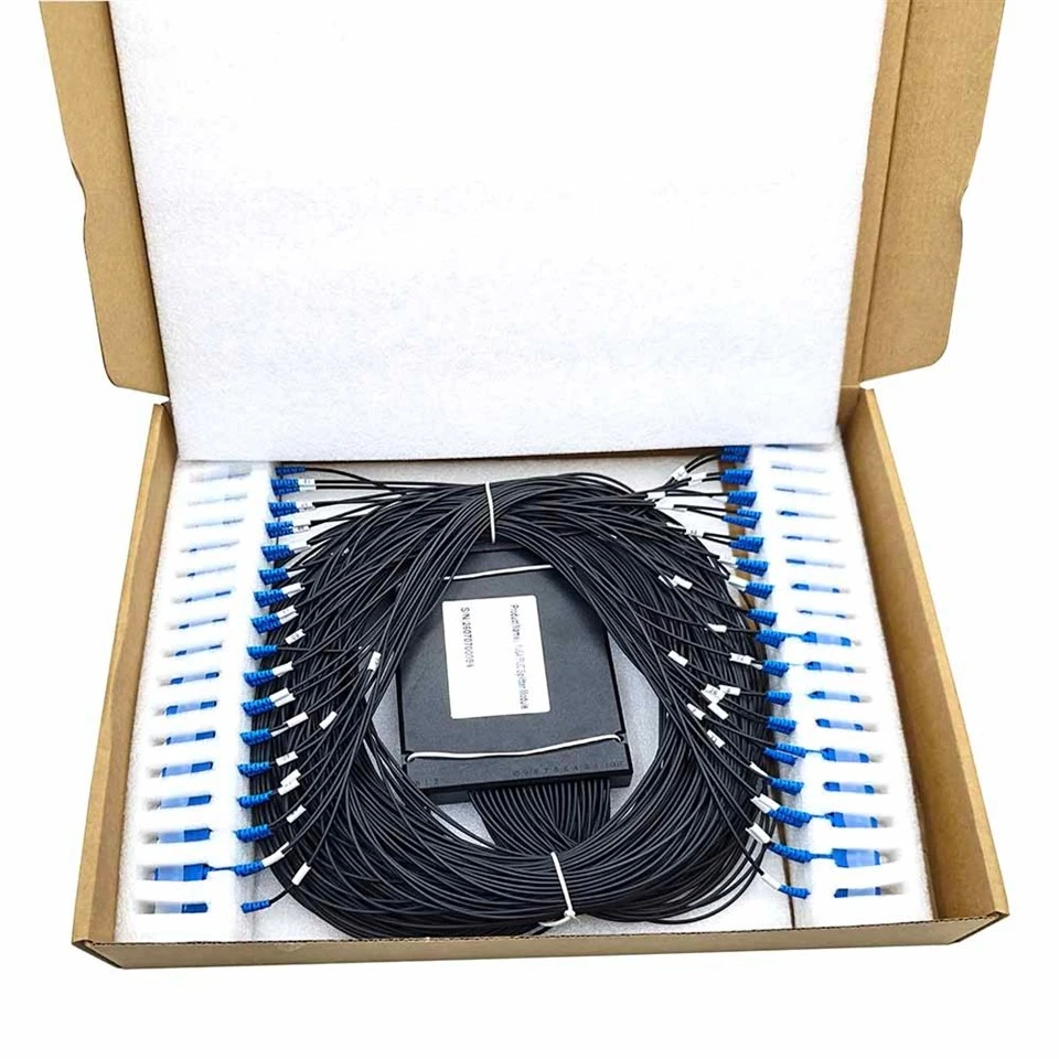
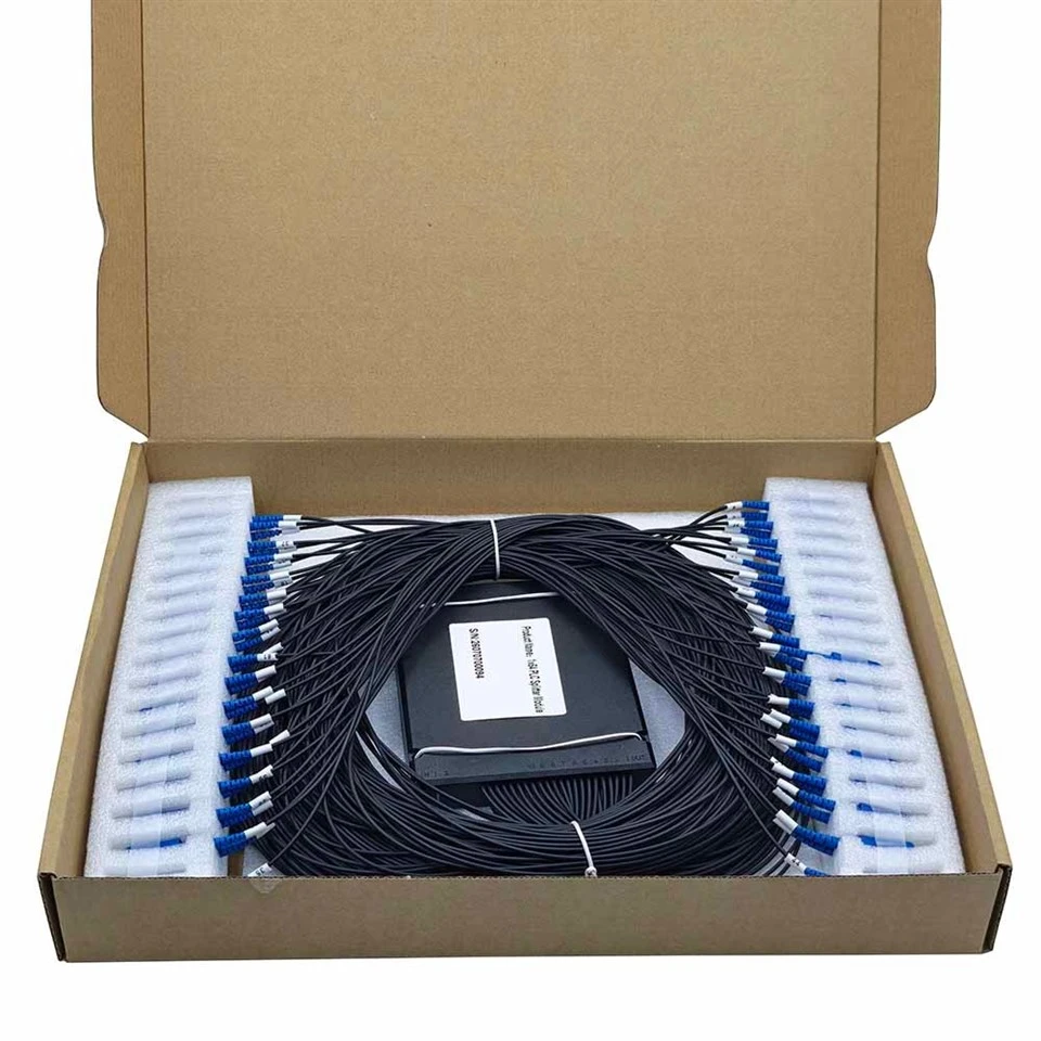
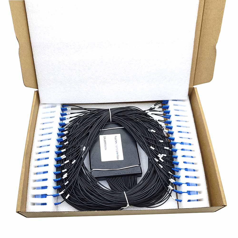
The photographed unit is supplied in a carton with the module centered inside a coiled lead arrangement. Connector ends are positioned in foam slots along the sides, and ties keep the fiber bundle organized. A foam layer is also visible inside the lid.
This arrangement separates the connector ends and keeps the leads together for handling. At receipt, check the carton, module label, connector protection and visible lead condition before removing the assembly. Release the ties and arrange the fibers without pulling on the connectors or forcing tight bends.
The photographs show the supplied sample's packing arrangement. Confirm the standard pack quantity, carton specification and any labeling requirements for your order.
Product Questions
Does the report cover every output port?
Yes. The supplied sample report lists Port 1 through Port 64 at 1310, 1490 and 1550 nm. It includes insertion-loss and polarization-dependent-loss entries and return-loss pass results. Specify the inspection coverage and documents required for delivered units in the purchase requirements.
Is 20.29 dB the guaranteed maximum insertion loss?
No. It is the highest insertion loss recorded in this sample's three-wavelength results. The report lists an insertion-loss limit of 20.40 dB. The acceptance value for an order should be agreed together with the test wavelengths and whether connector losses are included
How should the fiber length be specified?
The report lists fiber length as ≥2.0 m. For an order, state the required input length and output length separately, including tolerances and measurement reference points. This is particularly useful when the input and output routes have different space requirements
Can the numbered leads be matched to the inspection record?
The sample has numbered output leads, and its report lists results by port. Its module label also matches the serial number on the report. Confirm the port-numbering convention and the required serial-number-to-report relationship for your delivered assemblies.
Hot Tags: 1×64 plc splitter module, sc/upc, g.657.a1, China, factory, suppliers, manufacturers, quotation, customized, price, buy


