

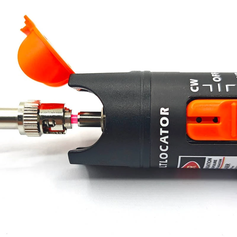
Welcome to buy the pen-type visual fault locator for fiber optic cable testing with our factory. As one of the leading manufacturers and suppliers in China, we also welcome the customized orders. Consult the price and the quotation with us now.
Connector Compatibility and Adapter Options
The right connection depends on the fiber connector and the VFL output interface. Check both before selecting the instrument, particularly when your work includes a mix of SC, FC, ST and LC patch cords.
Common SC, FC and ST connectors use 2.5 mm ferrules, while LC connectors use 1.25 mm ferrules. These sizes explain why an LC connection may need an additional adapter; they do not establish direct compatibility with every VFL.
Planning to test LC patch cords?
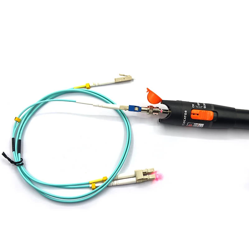
The LC connection shown in the product demonstration uses an additional coupling assembly. Specify LC in your inquiry and have the required adapter and its inclusion in the package confirmed.
For SC, FC or ST connections, provide the connector type and end-face finish. The order specification should identify the matching interface and any adapter required, rather than relying on a general "universal connector" description.
Fiber Identification, Continuity Checks and Visible Fault Tracing
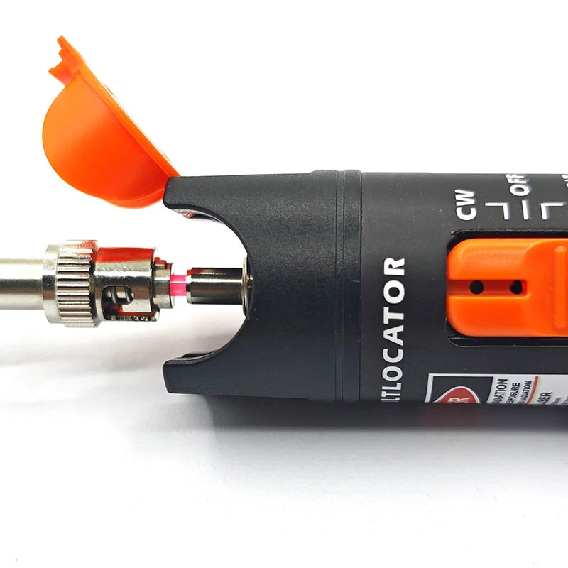
A VFL is useful when you need a visual answer at the cable, patch panel or accessible fiber section. Connect the fiber, select the operating mode and observe the relevant part of the route without looking into an optical port or fiber end.
Find the corresponding fiber end
Inject visible light into a disconnected fiber to help distinguish its opposite end from nearby fibers. This supports patch-cord identification and connection checks during installation or maintenance.
Establish a visual indication of continuity
Visible light at the far end indicates that light is passing through the fiber. If no light is visible, check the instrument, connection, viewing conditions and fiber path before concluding that the fiber is broken.
Look for accessible leakage points
Escaping red light can help reveal a break or a bend that causes light leakage where the fiber is accessible and the covering allows the light to be seen. Opaque jackets and enclosed routes can conceal these indications.
Operating Modes and Protective Cap
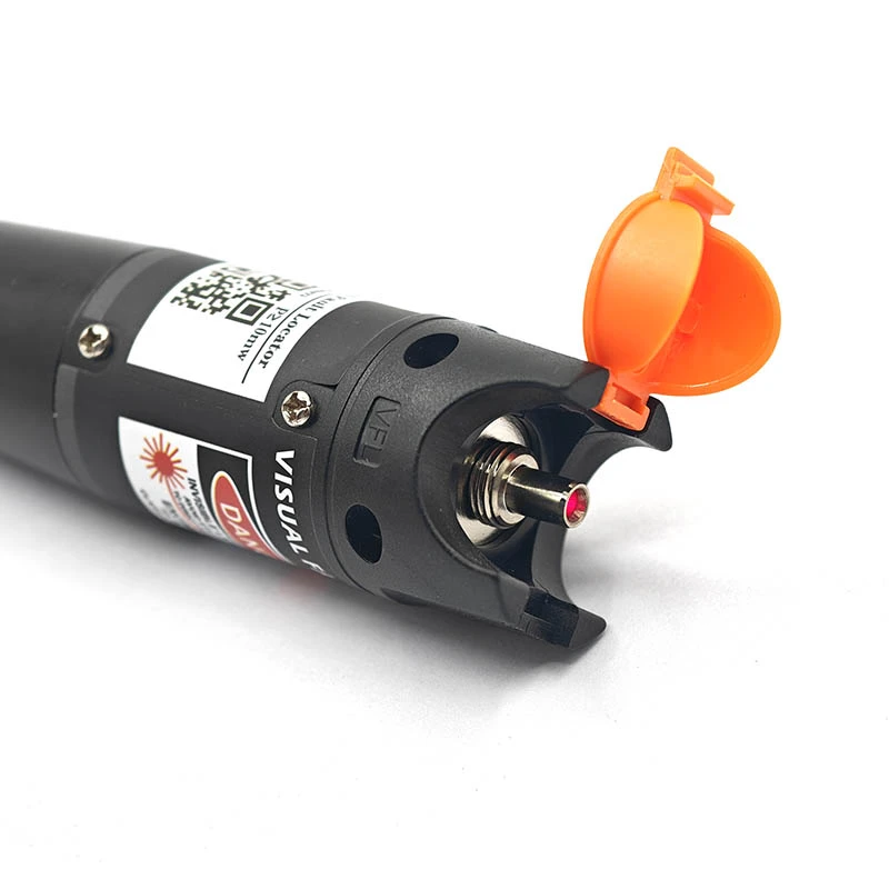
he slide switch is marked CW, OFF and GLINT. These positions identify continuous output, power off and flashing output. Choose the mode appropriate to the observation, following the instructions supplied for the ordered model.
- CW Continuous illumination for observing a fiber path or a visible leakage point.
- OFF Switch off before connecting, disconnecting or storing the instrument.
- GLINT Flashing illumination to help distinguish the test light. Confirm the flash rate if it is relevant to your procedure.
Open the cap, check that the connector and output interface are clean, and make the appropriate connection without forcing it. After the check, switch off, disconnect the fiber and close the cap. The cap covers the output during storage; it is not an indication of a waterproof rating.
Technical Specifications
| Item | Product detail / ordering requirement |
|---|---|
| Product type | Pen-type visual fault locator (VFL) |
| Visual output | Visible red light; request the nominal wavelength and tolerance for the quoted model. |
| Operating controls | CW / OFF / GLINT slide-switch markings; continuous, off and flashing positions. |
| Output cover | Orange flip-open protective cap |
| Connector interface | Specify SC, FC, ST or LC and the end-face finish. Confirm the output interface and required adapter combination. |
| Fiber type | State whether the application uses single-mode or multimode fiber and confirm suitability for the selected configuration. |
| Output power and laser class | Request the model-specific output rating and laser classification before ordering. |
| Visual test range | Confirm the rating and conditions for the quoted model. Fiber loss, connections, jacket construction and ambient light affect visibility. |
| Power supply and runtime | Confirm battery type, quantity, inclusion and runtime under the intended operating mode. |
| Dimensions and environment | Request dimensions, net weight, operating temperature and storage requirements if needed for procurement. |
Package Contents and Optional Accessories
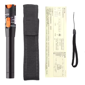
The photographed set shows the instrument alongside a carrying sleeve, wrist strap and paper instruction leaflet. Use this as a visual reference when agreeing the package for your order.
Pen-type visual fault locator
Fabric carrying sleeve
Wrist strap
Paper instruction leaflet
Confirm the final packing list on the quotation. Batteries and connector adapters are not established as included by this accessory photograph. If an LC adapter, a particular instruction language or a specific packing arrangement is required, include it in your inquiry.
Questions Before Ordering
Can I connect an LC patch cord directly?
Do not assume direct LC compatibility. The LC demonstration uses an additional coupling assembly. Provide your connector details so the matching adapter and whether it is included can be confirmed.
Can this VFL be used with single-mode and multimode fiber?
Both are common VFL applications, but suitability and visible range need to be confirmed for the actual model and fiber. State the fiber type in your inquiry rather than selecting the product from jacket color alone.
What determines how far I can see the test light?
Output power is one factor. Fiber attenuation at the test wavelength, connector losses, ambient light and the observation method also matter. Seeing light at a distant fiber end is different from seeing leakage through a cable jacket. Request the stated range and its conditions for the quoted model.
Does visible red light mean the link has passed a loss test?
No. It is a visual indication, not a loss measurement or link certification result. Use appropriate optical loss testing equipment to verify acceptance limits, or an OTDR when distance and event information are required.
Are batteries and connector adapters included?
The accessory photograph shows the VFL, carrying sleeve, wrist strap and instruction leaflet. Battery and adapter inclusion must be checked against the quotation. List any required adapters explicitly so they can be included in the agreed configuration.
Talk to FOCC
Hot Tags: pen-type visual fault locator for fiber optic cable testing, China, factory, suppliers, manufacturers, quotation, customized, price, buy


