

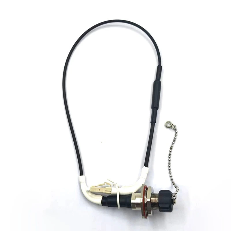
Welcome to buy the odc-2 to duplex lc om3 cable assembly with rear-mount hexagonal socket with our factory. As one of the leading manufacturers and suppliers in China, we also welcome the customized orders. Consult the price and the quotation with us now.
From the equipment panel to the internal LC ports
The ODC-2 end provides the panel connection, while the duplex LC end connects the two fibers to a compatible internal optical interface. This arrangement allows an external cable to terminate at the equipment boundary while a short, pre-terminated assembly completes the route inside the enclosure.
Select this configuration when the equipment already specifies an ODC-2 mating interface and an OM3 duplex LC connection internally. Useful installation locations include communication enclosures and equipment housings with a defined panel-to-module route. Fiber type, connector geometry and the optical requirements of the installed equipment must all match the selected assembly.
Where both ends of a link require an ODC receptacle, FOCC also offers an ODC socket-to-socket assembly. The version shown here uses duplex LC at the internal end, so the mating hardware and routing arrangement are different.
A rear-mount socket that starts with the panel drawing
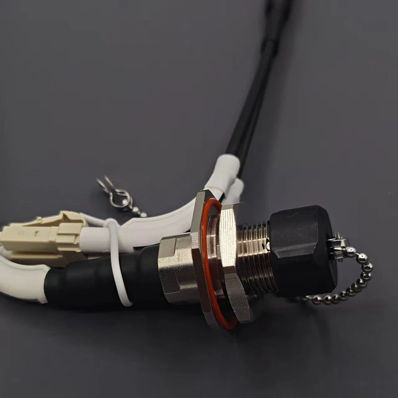
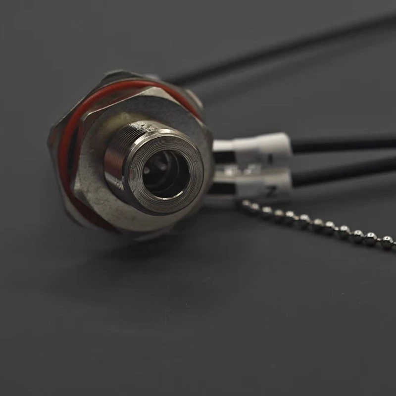
The socket has a threaded metal body and hexagonal mounting hardware. The photographs also show a red annular component at the mounting area. These details make the mounting interface an important part of product selection: the panel opening, available thread engagement and sealing arrangement must work together.
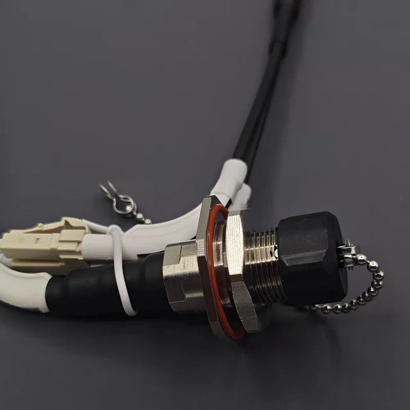
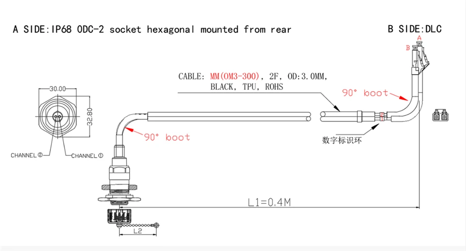
Check the panel thickness and cutout against the approved socket drawing before releasing the enclosure for manufacture. "Hexagonal" describes the mounting hardware shown; it does not specify a hexagonal panel opening. The 30.00 and 32.80 dimensions on the supplied front view describe the illustrated external geometry and should not be used as drilling dimensions.
Allow access behind the panel for the retaining hardware, the cable exit and the installation tool. Panel-nut tightening and connector coupling are separate operations, so each needs the appropriate instruction. A torque value published for a different ODC coupling should not be applied to this panel nut.
At the external interface, match the actual plug and socket variants, including their alignment features, optical contact arrangement and locking geometry. A shared ODC-2 description is a starting point for identification; the mating drawings establish the usable pair.
Two 90° boots for a defined internal cable route
Both ends are drawn with 90° boots. At the socket, the cable turns away from the connector axis; at the LC end, the angled boots direct the fibers away from the port axis. This geometry is useful when the internal route needs to follow an enclosure wall or approach a nearby module from the side.
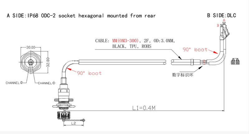
Plan that route with the equipment in its assembled state. The LC latches must remain accessible, the socket hardware needs clearance, and the cable should sit without being pulled taut. The angled boots establish the exit direction, but the cable beyond them still needs sufficient bend allowance.
The drawing specifies **L1 = 0.4 m** between the illustrated reference points. Use those same points when checking fit or ordering a different length. Measuring only the exposed cable can produce a different result. Include the intended service allowance in the route, particularly if a module must move during inspection or replacement.
The drawing identifies two ODC channels and shows numbered markers near the LC branches. For an unambiguous production drawing, record each ODC channel against its assigned LC position and define the viewing direction. This gives assembly and inspection teams a specific continuity map to check.
Keeping the exposed interface covered
The photographed socket has a removable black cap retained by a metal chain. During handling and storage, the cap covers the exposed interface, while the chain keeps it attached when removed. Leave enough space around the installed socket to remove and refit the cap without loading the cable or obstructing adjacent connections.
For environmental qualification, distinguish the panel seal, the plug-to-socket connection and the cap-to-socket connection. Each depends on its own mating surfaces and installation conditions. The IP68 designation on the socket drawing does not establish a protection rating for the exposed duplex LC end or for the complete equipment enclosure.
Specifications
|
Parameter |
Configuration |
|---|---|
|
Assembly |
ODC-2 socket to duplex LC |
|
Socket mounting |
Rear-mount, hexagonal hardware |
|
Optical channels |
2 |
|
Fiber type |
OM3 multimode; drawing designation: MM (OM3-300) |
|
Cable outer diameter |
3.0 mm |
|
Cable jacket |
Black TPU |
|
Socket-side boot |
90° |
|
LC-side boots |
90° |
|
Length |
L1 = 0.4 m, measured to the drawing reference points |
|
Channel identification |
ODC channel labels and LC-side number markers shown |
|
Socket cover |
Removable cap with retaining chain, as photographed |
|
Ingress protection designation |
IP68 on the A-side socket drawing; applicable assembly state and test conditions to be agreed |
|
Environmental compliance notation |
RoHS on the cable drawing; supporting declaration to match the ordered configuration |
Panel cutout, thread specification, panel thickness range, boot orientation and the channel-to-LC map belong on the approved order drawing. These dimensions and relationships are specific to the selected socket and equipment layout.
Optical performance and acceptance criteria
The two OM3 fibers provide separate optical paths between the ODC and LC interfaces. In a conventional duplex link, the completed channel assignment must connect each transmitter to the corresponding receiver. Check that assignment through the complete installed route, including any external cable and intermediate connections.
For initial optical budgeting, FOCC's related multimode ODC connector data provides a reference insertion loss of 0.25 dB typical and 0.50 dB maximum, with return loss of at least 20 dB for the listed multimode UPC interface. These are related-product connector figures, not measured results or guaranteed limits for this 0.4 m assembly. Their use also depends on confirming the selected optical contact and polish configuration.
The purchase specification should state the accepted loss for each finished fiber path, the test wavelengths, reference method and which connections are included in the measurement. For OM3, 850 nm and 1300 nm are conventional multimode test wavelengths; select the required wavelengths and launch conditions for the project. An individual connector figure should not be treated as the total loss of an assembly with different interfaces at its ends.
The drawing's "OM3-300" notation identifies the specified fiber designation. It does not, by itself, guarantee a network speed or a 300 m operating distance. System reach depends on the optical modules, transmission standard and complete channel budget.
IP68 qualification likewise needs defined conditions. Record the mating components, panel installation, connected or capped state, immersion depth and duration. Those conditions should appear in the relevant test documentation rather than being inferred from the rating alone.
Assembly and inspection for the ordered configuration
Production approval should begin with one drawing that fixes the two interfaces, L1 measurement points, exit directions and channel assignment. For this short assembly, a change in boot direction can affect equipment fit even when the overall length remains the same.
The inspection requirements should cover connector identification, mounting hardware, cable-jacket condition, cap retention, length and branch marking. Optical inspection should address end-face condition, continuity of both channels and insertion loss against the agreed acceptance limits. Where environmental verification is required, specify the test state and whether the requirement is design qualification, batch sampling or individual testing.
For repeat orders, associate the approved drawing revision and material configuration with the order or batch identification. If individual optical records are required, include the unit identifier, channel, wavelength, result and acceptance limit in the requested report. This makes the records useful for incoming inspection and later replacement.
Frequently asked questions
What panel opening does the socket require?
Use the installation dimensions for the selected socket. The hexagonal external dimensions in the supplied front view are not panel-hole dimensions. The approved drawing should include the cutout, tolerance, panel thickness range and sealing arrangement.
Can any ODC-2 plug be connected to this socket?
Compatibility needs to be checked against the actual mating interfaces. Confirm the plug and socket variants, alignment features, optical contacts and locking geometry. Similar product names or appearances do not establish interchangeability.
Does IP68 apply when the cap is fitted?
The current drawing does not identify the tested state. Confirm whether the supporting report covers a mated connection, a capped socket or both, and use the specified installation and immersion conditions.
How is the 0.4 m length measured?
It is the L1 dimension shown on the drawing, measured between its indicated reference points. It should not be replaced by a measurement of the visible cable alone.
How should the two channels be checked?
Define the ODC-to-LC mapping and viewing direction on the order drawing, then verify continuity for each path. Confirm transmit-to-receive routing through the completed equipment connection.
What records should be requested for batch acceptance?
Specify the approved drawing revision, configuration identification and optical results needed for each channel. Add material declarations and environmental test documentation where required by the project. Agree the reporting scope with the quotation.
Hot Tags: odc-2 to duplex lc om3 cable assembly with rear-mount hexagonal socket, China, factory, suppliers, manufacturers, quotation, customized, price, buy


