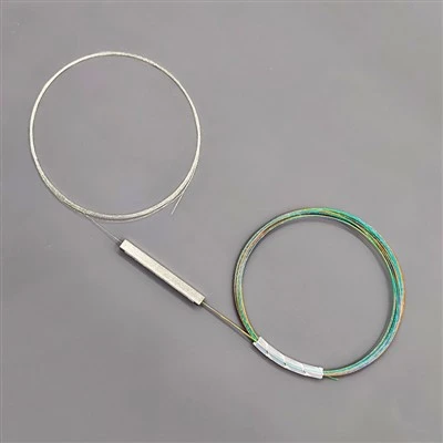
Welcome to buy the 1×8 bare fiber plc splitter for eight spliceable branches with our factory. As one of the leading manufacturers and suppliers in China, we also welcome the customized orders. Consult the price and the quotation with us now.
One Input, Eight Planned Branches
This splitter is intended for installations in which one optical input must be divided into eight output paths before the fibers are routed and fusion-spliced into the surrounding distribution assembly. That makes it a practical format to consider for an FTTH distribution box, splice tray or OEM fiber assembly with eight planned branches, provided the enclosure and optical budget suit the configuration.
The splitter package itself measures 40 × 4 × 4 mm according to the supplied data sheet. The installation footprint is larger than the metal package: it also includes one input lead, eight output leads, splice protection, routing loops and the space needed to close and service the enclosure. Check the complete tray layout rather than the package dimensions alone.
The product photographs show multiple colored output fibers leaving the package. Use the color and port mapping agreed in the assembly drawing or labeling plan. Confirm the mapping before splicing; a small labeling error becomes harder to find when eight branches leave the same input.
Check the 1×8 Loss Step Before Choosing the Splitter
The main selection difference between 1×4 and 1×8 is the number of branches and the resulting optical budget. An ideal equal split is approximately 6.02 dB for 1×4 and 9.03 dB for 1×8, so the 1×8 arrangement introduces roughly 3.01 dB more ideal splitting loss before excess loss, splices, connectors and transmission fiber are included.
| Selection point | 1×4 layout | 1×8 layout |
|---|---|---|
| Output branches | 4 | 8 |
| Ideal equal-split loss | About 6.02 dB | About 9.03 dB |
| Supplied configuration limit | ≤7.10 dB IL | ≤10.20 dB IL |
| Output routing to plan | 4 paths | 8 paths |
The ideal values are calculation references, not acceptance limits for a finished link. Use the 1×8 insertion-loss limit in the project budget and then add the losses from fiber, fusion splices, connectors and other passive components. Include the required engineering margin before deciding whether an eight-way split is suitable.
Eight Outputs Change the Installation Checklist
An eight-way splitter needs a little more planning around the fiber than a four-way unit. The installation team should confirm the following before the enclosure is closed:
- The layout has room for nine fiber paths: one input and eight outputs.
- The eight output ports are numbered before splicing and match the assembly drawing.
- Each completed fusion splice has a compatible protection sleeve and a defined tray position.
- The fiber routes leave enough service slack without crossing the cover, retaining points or sharp edges.
- The package exits are supported without pulling on the bare fiber leads.
- The output color sequence and port labels are checked during receiving and again after assembly.
G.657.A2 is the fiber type listed on the supplied sheet. Even in compact fiber equipment, it does not remove the need to follow the applicable bend-radius and handling requirements. Keep tight bends and pulling forces away from the package exits.
Port-Level Balance, Not Just a Single Loss Number
The supplied inspection sheet is dated **29 July 2026** and identifies sample S/N **26072900012**. It records insertion loss and PDL for all eight output ports at 1310, 1490 and 1550 nm. The following table summarizes the sample sheet.
|
Test Wavelength |
IL Across the Eight Output Ports |
Average IL |
Uniformity |
Highest Recorded PDL |
|---|---|---|---|---|
|
1310 nm |
9.71–10.09 dB |
9.90 dB |
0.38 dB |
0.09 dB |
|
1490 nm |
9.64–10.06 dB |
9.81 dB |
0.42 dB |
0.09 dB |
|
1550 nm |
9.66–10.07 dB |
9.85 dB |
0.41 dB |
0.08 dB |
The sample uniformity values remain within the stated ≤0.8 dB limit. Uniformity is the difference between the highest and lowest output-port insertion loss at the same wavelength; it helps show how evenly the eight branches are balanced. The sheet marks the return-loss result for each output as Pass against the >55 dB requirement. It does not provide a separate numerical return-loss value for each port.
These figures are the results shown on the supplied sample sheet. Use the inspection document supplied for the relevant shipment or unit when applying a project acceptance requirement. If your purchasing specification requires individual test sheets for every unit, state that requirement in the inquiry and confirm the supplier's documentation policy for this SKU.
Optical and Physical Specifications
The 1×8 Bare Fiber PLC Splitter is designed to distribute one optical input signal across eight output channels. It features G.657.A2 fiber leads, a compact 40 × 4 × 4 mm splitter package, and a broad operating wavelength range of 1260–1650 nm.
The following table summarizes the main optical and mechanical specifications for technical evaluation and procurement reference.
| Parameter | Specification |
|---|---|
| Product Type | Bare Fiber Planar Lightwave Circuit (PLC) Splitter |
| Splitter Configuration | 1×8 (1 Input, 8 Outputs) |
| Part Number | 1x8-0.25-2.5M |
| Connector Configuration | Unconnectorized (Bare Fiber) |
| Fiber Type | G.657.A2 |
| Fiber Lead Length | ≥ 2.5 m |
| Splitter Package Dimensions | 40 × 4 × 4 mm |
| Operating Wavelength Range | 1260–1650 nm |
| Inspection Wavelengths | 1310 / 1490 / 1550 nm |
| Insertion Loss (IL) | ≤ 10.20 dB |
| Polarization-Dependent Loss (PDL) | ≤ 0.20 dB |
| Loss Uniformity | ≤ 0.80 dB |
| Return Loss (RL) | > 55 dB |
| Directivity | > 55 dB |
| Operating Temperature | −40 to +85 °C |
| Storage Temperature | −40 to +85 °C |
Optical performance limits apply at the specified inspection wavelengths of 1310 nm, 1490 nm, and 1550 nm.
Part Number Clarification: The part number includes the designation 0.25. Before publishing this as a 250 μm coated-fiber diameter specification, confirm its exact meaning with the technical or production team. The final product description should remain consistent with the approved product drawing, quotation, and inspection documentation.
1×4 vs. 1×8 PLC Splitter: Which Configuration Should You Choose?
The choice between a 1×4 and a 1×8 PLC splitter depends primarily on the required number of distribution branches, available optical power budget, and installation arrangement.
A 1×4 PLC splitter is suitable for distribution networks requiring four output connections. Its lower splitting ratio generally results in lower theoretical splitting loss, making it a practical choice when fewer branches are needed.
A 1×8 PLC splitter is designed for applications where one optical input must serve eight downstream connections. It provides greater distribution capacity through a single splitter, helping reduce the need for multiple splitting devices in suitable network layouts.
Before selecting either configuration, consider the following factors:
Output capacity: Match the splitter ratio to the actual number of downstream connections.
Optical power budget: Account for splitting loss, connector loss, splice loss, and other losses throughout the optical link.
Installation space: Check whether the splitter package and fiber routing fit the available enclosure.
Future expansion: Consider whether additional output branches may be required as the network develops.
The key is to select the splitting ratio based on actual network requirements rather than output count alone.
Protective Packaging and Receiving Inspection
The 1×8 Bare Fiber PLC Splitter is supplied in a protective tray with transparent packaging and white cushioning inserts. The compact splitter package is positioned between the coiled input and output fiber leads, helping maintain an organized arrangement during handling and transportation.
For bare fiber components, proper handling is particularly important because the fiber leads do not have connector housings to provide additional mechanical protection.
During receiving inspection, buyers and assembly technicians should check:
Product identification: Verify the part number and product configuration against the purchase order.
Fiber condition: Check the fiber leads for visible damage, sharp bends, or abnormal deformation.
Package condition: Inspect the splitter package and protective tray for signs of damage during transportation.
Lead arrangement: Confirm that the fiber lead length and output configuration match the approved requirements.
Inspection documentation: Verify that the supplied optical test records correspond to the delivered product.
During unpacking and installation, support the splitter package and release the fiber coils carefully. Avoid pulling the fiber leads directly from the package exits or applying excessive bending force.
These handling precautions help reduce the risk of fiber damage before splicing and final installation.
Customization and Ordering Requirements for 1×8 PLC Splitters
To ensure the supplied splitter matches your network design and installation requirements, provide the key configuration details when requesting a quotation.
For the 1×8 Bare Fiber PLC Splitter, the reference part number is 1x8-0.25-2.5M. Buyers can use the following information as a specification checklist:
| Ordering Information | Details to Confirm |
|---|---|
| Required Quantity | Total units required for the project |
| Fiber Type | G.657.A2 or other approved fiber requirements |
| Fiber Lead Length | Standard ≥2.5 m or project-specific length |
| Fiber Diameter | Confirm coated fiber diameter and construction |
| Splitter Package | 40 × 4 × 4 mm or approved alternative |
| Optical Requirements | IL, PDL, uniformity and RL limits |
| Inspection Wavelengths | 1310 / 1490 / 1550 nm |
| Port Identification | Output numbering, color coding and labeling |
| Test Documentation | Individual unit test sheet or batch inspection report |
| Packaging Requirements | Protective tray, labeling and serial-number identification |
For projects involving existing fiber distribution boxes, ODF units, or compact optical enclosures, providing an installation drawing or dimensioned photograph is recommended. This allows the supplier to review package clearance, fiber routing, and available splice-holder positions before production.
Request a Quote for Your 1×8 Bare Fiber PLC Splitter
Send FOCC your required quantity, fiber specifications, lead length, and optical performance requirements. Our team can review your configuration and provide product details, technical documentation, and a quotation based on your project requirements.
Hot Tags: 1×8 bare fiber plc splitter for eight spliceable branches, China, factory, suppliers, manufacturers, quotation, customized, price, buy