

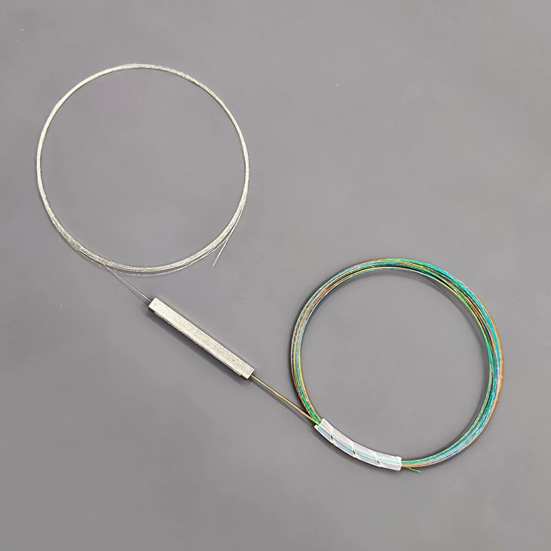

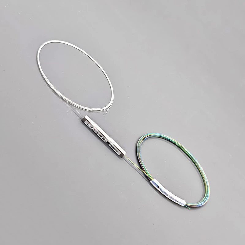
Welcome to buy the 1×4 bare fiber plc splitter, g.657.a2, 40 × 4 × 4 mm with our factory. As one of the leading manufacturers and suppliers in China, we also welcome the customized orders. Consult the price and the quotation with us now.
Built for Spliced Fiber Distribution
For a distribution assembly built around fusion splices, this bare fiber format provides leads that can be routed and spliced within the equipment. Typical integration points include FTTH distribution boxes, splice trays and OEM fiber distribution assemblies where the splitter package and fiber paths can be secured inside a protective enclosure.
The 40 × 4 × 4 mm dimensions describe the splitter package. Allow additional space for fiber routing, splice protection sleeves and service loops when checking the fit within a tray or terminal box. A package that fits the mounting position still needs a suitable route for all five fiber leads.
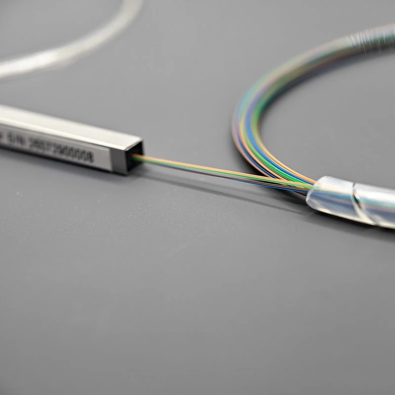
The colored output fibers help installers distinguish the four output paths during handling. Agree the port-to-color mapping when preparing an assembly drawing or labeling plan. The G.657.A2 fiber is bend-insensitive, but routing should still follow the applicable fiber handling and minimum bend-radius requirements. Keep tension and tight bends away from the fiber exits.
Optical and Physical Specifications
The following specifications apply to the 1×4, 250 μm, unconnectorized configuration. The optical inspection sheet records testing at 1310, 1490 and 1550 nm; these test points are listed separately from the operating wavelength range.
| Parameter | Specification |
|---|---|
| Product type | Bare fiber planar lightwave circuit (PLC) splitter |
| Splitter configuration | 1 input × 4 outputs |
| Part number | 1x4-0.25-2.5M |
| Connector configuration | Unconnectorized |
| Fiber type | G.657.A2 |
| Coated fiber diameter | 250 μm / 0.25 mm |
| Fiber lead length | ≥2.5 m |
| Splitter package dimensions | 40 × 4 × 4 mm |
| Operating wavelength range | 1260–1650 nm |
| Inspection wavelengths | 1310 / 1490 / 1550 nm |
| Insertion loss (IL) | ≤7.10 dB at the inspection wavelengths |
| Polarization-dependent loss (PDL) | ≤0.20 dB at the inspection wavelengths |
| Loss uniformity | ≤0.60 dB at the inspection wavelengths |
| Return loss (RL) | >55 dB |
| Directivity | >55 dB |
| Operating temperature | −40 to +85 °C |
| Storage temperature | −40 to +85 °C |
| Inspection documentation | Individual test sheet supplied with each unit |
For a network loss budget, include the splitter insertion loss together with the losses from transmission fiber, splices, connectors and any additional passive components. Apply the project's required margin before selecting the complete link configuration. The 250 μm dimension refers to the coated fiber diameter.
What the Supplied Test Sheet Shows
The sample inspection sheet dated 29 July 2026 provides measured insertion-loss and polarization-dependent loss (PDL) results for all four output ports at 1310 nm, 1490 nm, and 1550 nm. These measurements help buyers evaluate the optical performance, output consistency, and compliance of the 4-port PLC splitter against its stated acceptance criteria.
|
Test Wavelength |
Insertion Loss Across Four Outputs |
Loss Uniformity |
Highest Recorded PDL |
|---|---|---|---|
|
1310 nm |
6.67–6.93 dB |
0.26 dB |
0.07 dB |
|
1490 nm |
6.54–6.95 dB |
0.41 dB |
0.09 dB |
|
1550 nm |
6.52–6.90 dB |
0.38 dB |
0.07 dB |
The recorded results show that all four output ports meet the specified insertion-loss and PDL limits at all three inspection wavelengths. Loss uniformity also remains within the specified maximum of 0.60 dB, with measured values ranging from 0.26 dB to 0.41 dB. This indicates that the insertion-loss differences between the four output paths remain within the stated acceptance threshold across the tested wavelengths.
For a PLC splitter, output consistency matters because uneven optical power distribution can affect the available power budget of individual downstream links. The recorded uniformity results therefore provide buyers with a practical reference for assessing how consistently the sample distributes optical power across its four outputs. The PDL measurements offer an additional indication of how much insertion loss varies with the polarization state of the input signal.
The inspection sheet also records a Pass result for return loss at each output port against the requirement of greater than 55 dB. However, it does not provide individual numerical return-loss measurements, so the available evidence confirms compliance with the stated pass/fail criterion rather than the precise return-loss value of each port.
These results apply to the inspected sample unit and should not be interpreted as a guarantee that every production unit will deliver identical measurements. For procurement qualification, buyers should compare the results with the approved product specifications and review the corresponding test records supplied with each production batch or unit, where applicable. This approach provides a more reliable basis for evaluating product acceptance and maintaining quality consistency across deployed optical networks.
Packaging and Fiber Handling
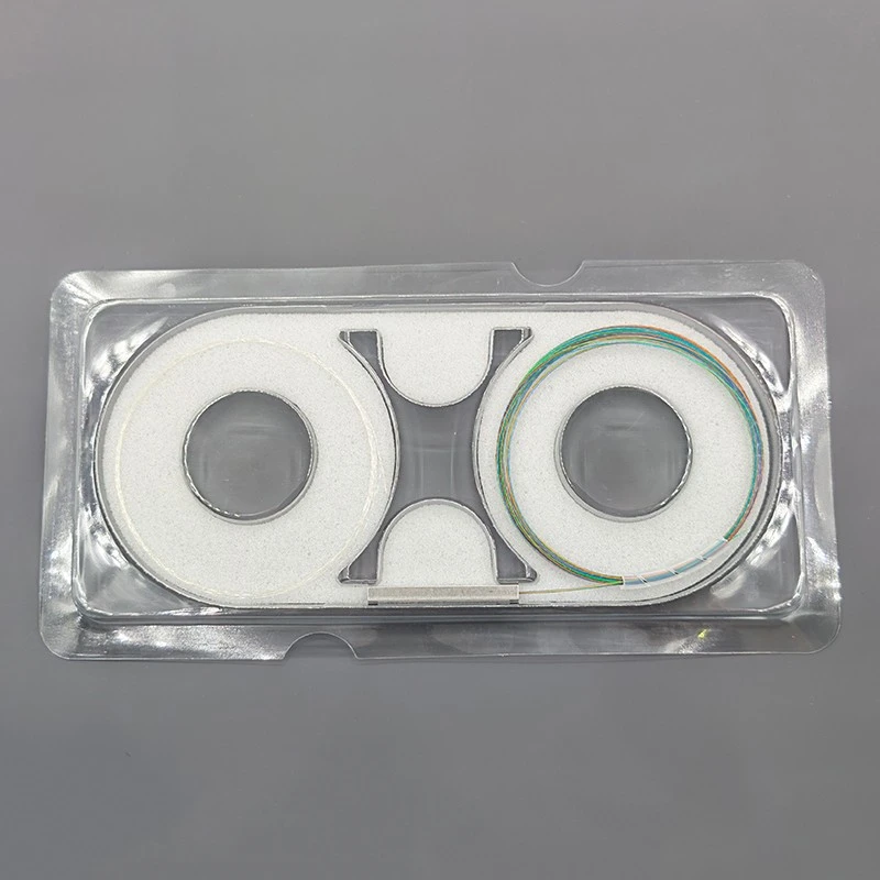
The splitter is presented in a clear protective tray with white cushioning inserts. The fiber leads are coiled on either side, with the labeled splitter package positioned between the coils. This arrangement keeps the package and fiber coils organized for unpacking and inspection.
On receipt, check the product identification, required configuration and accompanying test sheet before moving the splitter into an assembly. Support the package while releasing the coils, and avoid pulling on the fibers at the package exits.
During installation, route the leads through the intended tray paths, protect each completed fusion splice and secure the splitter package in a suitable holder. Use the relevant fiber and enclosure instructions to establish the routing radius. Leave enough slack for assembly and servicing without trapping the fibers beneath a cover or retaining clip.
FAQ
What is the difference between a bare fiber splitter and a connectorized splitter?
A bare fiber splitter has unconnectorized fiber leads that are typically fusion-spliced into the installation. A connectorized splitter has terminated leads that plug into compatible adapters. This FOCC model uses 250 μm coated fiber leads for splicing. Choose the format to match the enclosure, connection method and maintenance needs of your project.
What insertion loss should I allow for this 1×4 splitter?
The specified insertion loss is ≤7.10 dB at 1310, 1490 and 1550 nm. An ideal equal four-way split accounts for approximately 6.02 dB of splitting loss before additional device losses. For network planning, use the specified maximum and add the losses from fiber, splices, connectors and other components, together with the required system margin.
What fiber type, diameter and length does this model use?
This configuration uses G.657.A2 fiber with a 250 μm coated diameter and a specified fiber lead length of at least 2.5 m. The leads are unconnectorized. For an assembly with different input and output length requirements, state each length separately in the inquiry so the quotation can address the intended layout.
Will the 40 × 4 × 4 mm splitter fit inside my distribution box?
The 40 × 4 × 4 mm dimensions describe the splitter package. The installation also needs space for five fiber leads, routing loops, splice protection sleeves and a suitable mounting position. Check the complete tray layout, including clearance beneath the cover, before confirming compatibility. A drawing or dimensioned photograph helps establish whether the assembly has sufficient space.
Can I cascade this splitter with another optical splitter?
Yes, PLC splitters can be used in a cascaded distribution design, provided the total splitting arrangement and optical losses meet the network requirements. Add the loss of each splitter along the path, together with all fiber, splice and connector losses. Also check the permitted split ratio, equipment optical budget and operating margin before selecting the cascade.
Does G.657.A2 fiber allow unrestricted bending during installation?
G.657.A2 is bend-insensitive fiber, but it still requires controlled routing and careful handling. Follow the applicable minimum bend-radius requirements, avoid tight bends at the package exits and keep pulling forces off the leads. Secure the splitter package and protect completed fusion splices before closing the enclosure.
Can the splitter be installed outdoors?
The bare splitter should be installed within an enclosure that provides the environmental protection required by the site. Its specified operating temperature is −40 to +85 °C, but that temperature rating does not establish water or dust protection for the complete installation. Outdoor suitability depends on the enclosure, cable-entry sealing, internal mounting and fiber protection.
Hot Tags: 1×4 bare fiber plc splitter, g.657.a2, 40 × 4 × 4 mm, China, factory, suppliers, manufacturers, quotation, customized, price, buy


